AIR CONDITIONING
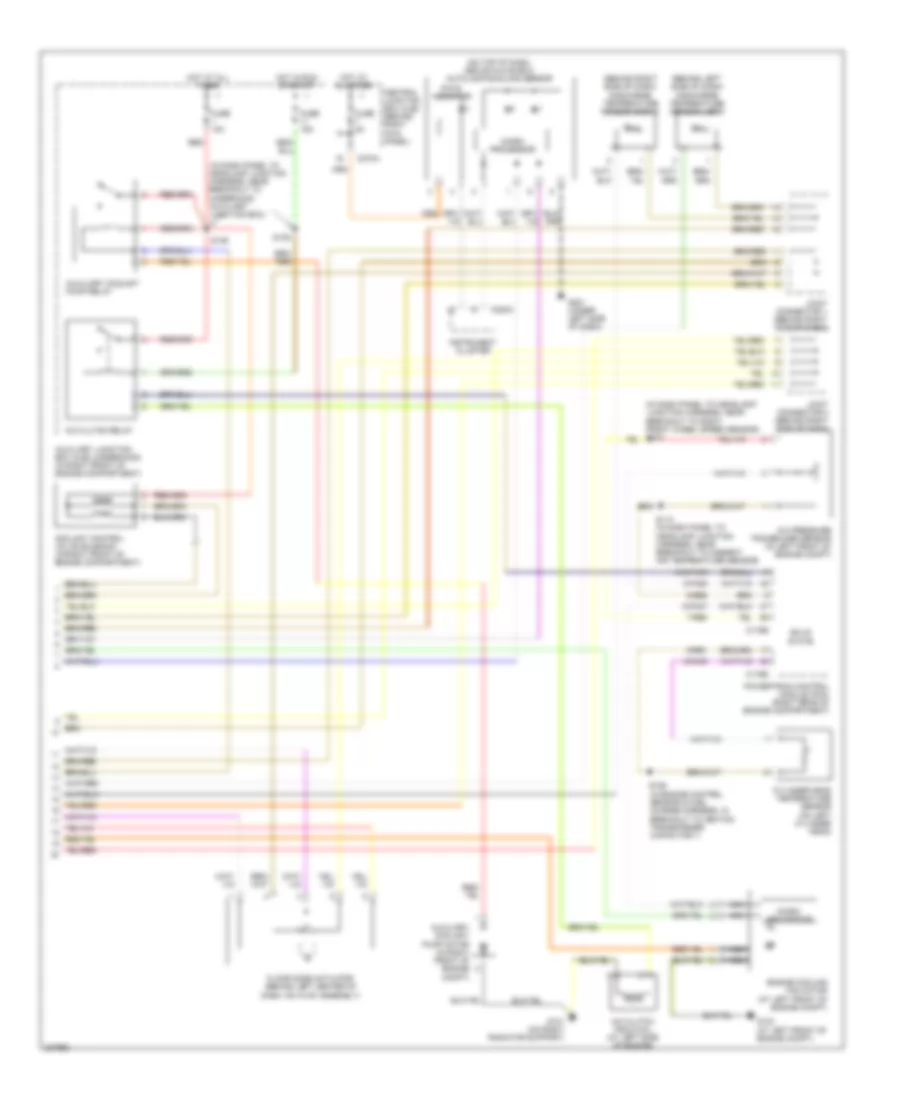
Automatic A/C Wiring Diagram (1 of 2) for Lincoln LS 2006

List of elements for Automatic A/C Wiring Diagram (1 of 2) for Lincoln LS 2006:
- (at right front of engine compt) ambient air temperature sensor
- (behind center of dash) evaporator discharge air temperature sensor
- (behind right side of dash) joint connector 1
- (in air conditioning harness, near breakout to heater blower motor) s214
- (in dash panel to headlamp junction harness, near breakout to right front foglight) s104
- (on bottom of right side "a" pillar) g204
- 10-fa53
- 20-fa10
- 29-fa10
- 30s-fa45
- 31-fa10
- 31-fa45
- 31s-fa18
- 31s-fa23
- 32-fb5
- 32-fb6
- 32-fb7
- 32-fb8
- 33-fb5
- 33-fb6
- 33-fb7
- 33-fb8
- 4-fa1
- 4-fa10
- 5-fa10
- 60a
- 7-fa1
- 8-fa44
- 8-fa45
- 8-fa47
- 8-fa48
- 8-fa49
- 8-fa51
- 8-fa53
- 8-fb5
- 8-fb6
- 8-fb7
- 8-fb8
- 9-fa2
- 9-fa3
- 9-fa44
- 9-fa48
- 9-fa49
- 9-fb8
- 91s-fa76
- 91s-fb3
- 91s-fb4
- 91s-hb7
- Auxiliary junction box (ajb) (underhood) (in right front of engine compartment)
- Blower motor relay
- C228a
- C228b
- C270a
- Central junction box (cjb) (behind right kick panel)
- Data link connector (dlc) (under left side of dash)
- Defogger system
- Defrost mode actuator (behind right side of dash, on hvac assembly)
- Electronic automatic temperature control (eatc) module (behind center of dash)
- Fresh/recirculation door actuator (behind right side of dash, on hvac assembly)
- Fuse 10a
- Fuse 15a
- Fuse 30a
- Fuse 5a
- G201 (under left side of dash)
- Heater blower control module (behind right center of dash)
- Heater blower motor (behind right center of dash)
- Hot at all times
- Hot in run
- Hot in run or start
- In-line fuse (at right kick panel)
- In-vehicle temperature sensor (behind center of dash)
- Joint connector 4 (behind left
- Panel mode actuator (behind right side of dash, on hvac assembly)
- Side of dash)
- Solid state
Automatic A/C Wiring Diagram (2 of 2) for Lincoln LS 2006
List of elements for Automatic A/C Wiring Diagram (2 of 2) for Lincoln LS 2006:
- (behind left side of dash) discharge temperature sensor (left)
- (behind right side of dash) discharge temperature sensor (right)
- (in dash panel to headlamp junction harness, near breakout to underhood auxiliary junction box)
- (in engine control sensor & fuel charge harness, in breakout to ignition transformer capacitor 1)
- (on top of dash, above glove box) autolamp/sunload sensor
- 7-re8
- 8-fa88
- 8-pa47
- 8-rj33
- 9-re1
- 9-re8
- 91s-fa79
- A/c clutch field coil (at left side of engine)
- A/c clutch relay
- A/c pressure transducer sensor (in left front of engine compt)
- Auxiliary coolant pump motor (in right front of engine compt)
- Auxiliary coolant pump relay
- Auxiliary junction box (ajb) (underhood) (in right front of engine compartment)
- C175b
- C175e
- C220a
- C270a
- Central junction box (cjb) (behind right kick panel)
- Coolant control valve solenoid (in right front of engine compartment)
- Cylinder-head temperature sensor (on left cylinder head)
- Engine cooling fan motor (at left front of engine compt)
- Floor mode actuator (behind left center of dash, on hvac assembly)
- Fuse 10a
- Fuse 15a
- Fuse 5a
- G101 (on right radiator support)
- G103 (at left front of engine compt)
- G201 (under left side of dash)
- Hot at all times
- Hot in run or start
- Instrument cluster
- Joint connector 1 (behind right side of dash)
- Joint connector 2 (behind right side of dash)
- Micro- processor
- Nca
- Pats indicator
- Powertrain control module (pcm) (right rear of engine compartment)
- Red
- S113 (in dash panel to headlamp junction harness, near breakout to ambient air temperature sensor)
- S126
- S135
- S136
- Solid state