AIR CONDITIONING
Air Conditioning Wiring Diagrams for Lincoln Mark VIII LSC 1997
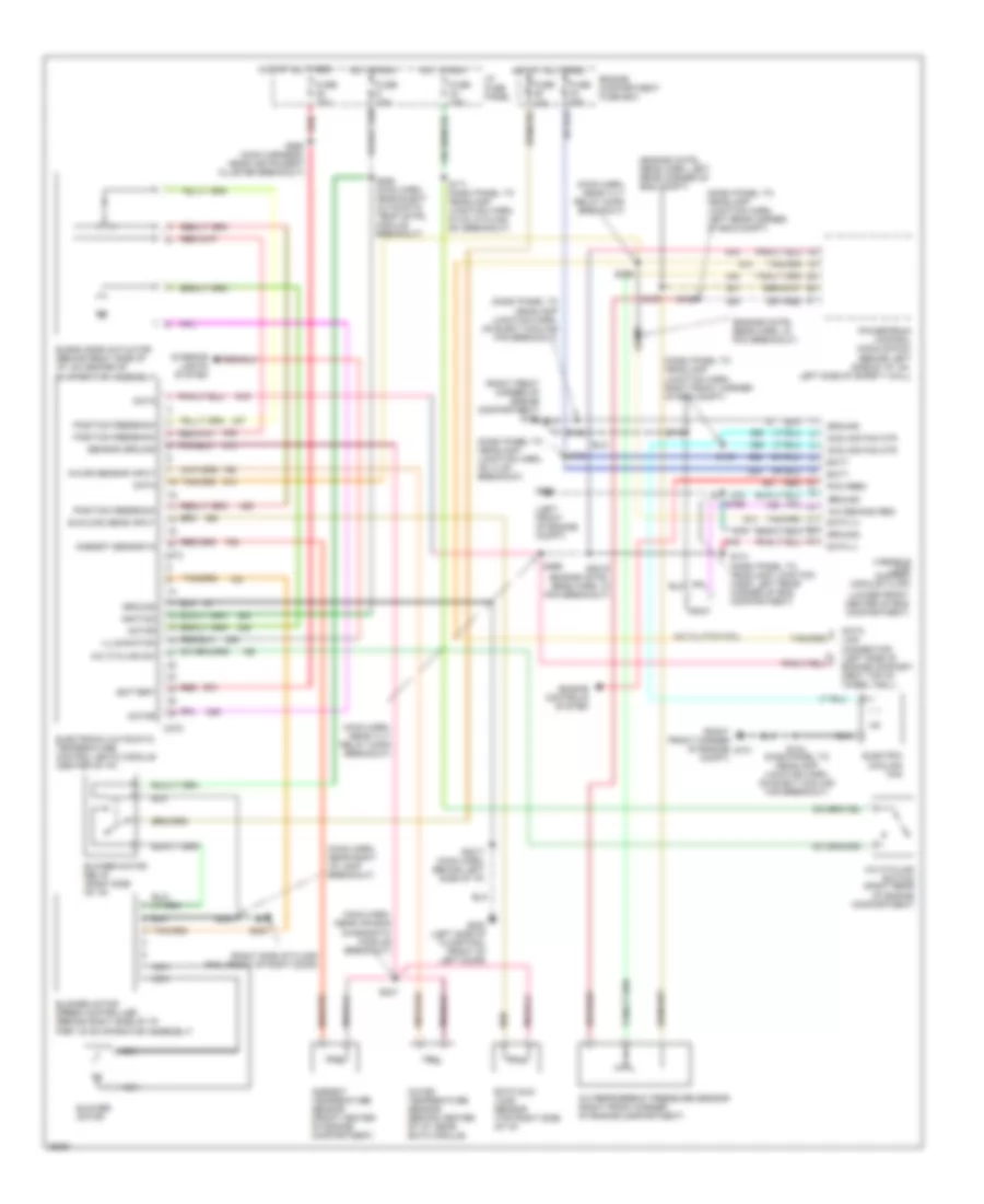
List of elements for Air Conditioning Wiring Diagrams for Lincoln Mark VIII LSC 1997:
- (dash panel to headlamp junction harn, left rear corner of eng compt)
- (dash panel to headlamp junction harn, on elect cooling fan breakout)
- (dash panel to headlamp junction harn, on vlcm breakout)
- (dash panel to headlamp junction harn, right front corner of eng compt)
- (engine cntrl sens harn, in pcm breakout)
- (engine cntrl sens harn, left rear corner of eng compt)
- (left front of engine compt)
- (lower front center of eng compartment)
- (main harn, near air bag diagnostic module breakout)
- (main harn, near right i/p lamp breakout)
- (main harn, near tilt relay conn breakout)
- (right front corner of engine compartment) g101
- (right front corner of engine compt)
- (right side of floor pan, front of right door)
- A/c clutch coil
- A/c cycling sw
- A/c cycling switch (right rear of engine compartment)
- A/c demand req
- A/c refrigerant pressure sensor (right front corner of engine compartment)
- Ambient sensor in
- Ambient temperature sensor (front center of engine compartment)
- Batt
- Battery
- Blend door actuator (behind right side of i/p, on center of
- Blower motor
- Blower motor relay (right side of i/p)
- Blower motor speed controller (behind right side of i/p,
- C272
- C273
- Cooling fan mtr
- Data
- Data (+)
- Data (-)
- Eatc sun load sensor (top right side of i/p)
- Electric cooling fan
- Electronic automatic temperature control (eatc) module (center of i/p)
- Engine compartment fuse box
- Engine controls system
- Evaporator assembly)
- Fuse 10a
- Fuse 15a
- Fuse 40a
- G100
- G101
- G200 (left side of floor pan, front of left door)
- G203
- Ground
- Hot at all times
- Hot in run
- I/p fuse panel
- Ignition
- Illumination
- In-car sensor input
- In-car temperature sensor (behind center of i/p, near eatc module)
- Interior lights system
- Link connector (left side of engine compart- ment top of wheel well)
- Motor
- Nca
- Part of evaporator assembly)
- Pcm feed
- Position feedback
- Powertrain control module (pcm) (behind left side of i/p, on left side of safety wall)
- Red
- S104
- S137
- S139
- S141 (dash panel to headlamp junction harn, left rear corner of eng compartment)
- S156
- S161
- S165
- S171 (dash panel to headlamp junction harn, in a/c cycling sw breakout)
- S172
- S2017 (main harn, behind left side of i/p)
- S2019 (engine cntrl sens harn, in pcm breakout)
- S2020
- S208
- S247
- S288 (main harn, near elect automatic temp cntrl module breakout)
- S292 (main harness, near instrument cluster breakout)
- S295
- S296
- Sensor ground
- Sunload sens input
- Variable load control module (vlcm)
 English