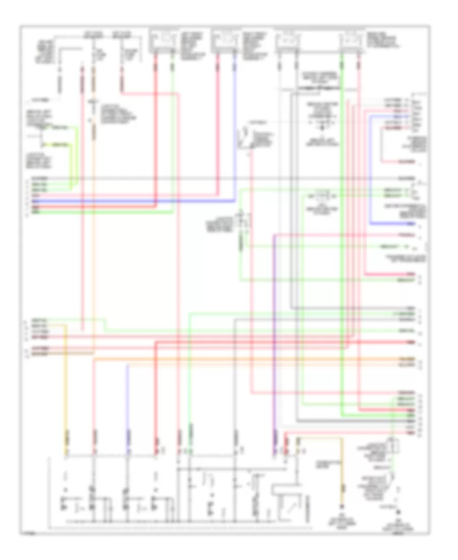
ANTI-LOCK BRAKES
Anti-lock Brakes Wiring Diagram (1 of 3) for Lexus GX 470 2003

List of elements for Anti-lock Brakes Wiring Diagram (1 of 3) for Lexus GX 470 2003:
- (behind upper left end of dash) junction connector 9
- (in dash harness, behind left side of dash)
- (in eng harn, at left side of engine compartment)
- (on right front inner fender) ea
- +b1
- +bo
- Abs & ba & trac & vsc actuator (at left of engine compt, beside brake master cylinder)
- Abs mtr fuse 40a
- Abs mtr relay
- Abs sol fuse 50a
- Abs sol relay
- Ast
- Dac relay
- Driver side j/b (behind lower left end of dash)
- E24
- Eb (on left front inner fender)
- Ecu-b fuse 10a
- Engine room r/b (on left side of engine compartment)
- Fl+
- Fl-
- Fr+
- Fr-
- Fss
- Gnd
- Gnd1
- Gnd2
- Hdcw
- Hot at all times
- Ig2
- J12
- Junction connector 22 (behind right side of dash)
- Junction connector junction connector (near battery)
- Master cylinder pressure sensor (on master cylinder reservoir)
- Mr1
- Mr2
- Mss
- Mt+
- Mt-
- Mtt
- Nca
- Pmc
- Pnk
- R1+
- R2+
- Red
- S11
- Sa1
- Sa2
- Sa3
- Sflh
- Sflr
- Sfrh
- Sfrr
- Skid control ecu (behind left end of dash, above driver side j/b)
- Srlh
- Srlr
- Srrh
- Srrr
- Stop fuse 10a
- Stoplight switch (behind left side of dash, above brake pedal)
- Stp2
- Stpo
- Str
- Trc mtr relay
- Trig
- Vcm
- Vout
Anti-lock Brakes Wiring Diagram (2 of 3) for Lexus GX 470 2003
List of elements for Anti-lock Brakes Wiring Diagram (2 of 3) for Lexus GX 470 2003:
- (behind center of dash) junction connector 14
- (behind left end of dash) junction connector 8
- (in dash harness, behind left side of dash)
- Abs ind
- Bat
- Brake ind
- C10
- C11
- C21
- Center differential lock ecu (behind right side of dash)
- Combination meter
- Dac ind
- Detection switch (transfer l4 position) (on trans housing)
- Downhill assist control switch
- Driver side j/b (behind lower left end of dash)
- E23
- Ee (on rear of right cylinder head)
- Eg (on rear of left cylinder head)
- Ess
- Gauge fuse 7.5a
- Hot in on or start
- I10
- Ig1
- Ign fuse 10a
- Ij (behind left center of dash)
- Ind
- J/b 2 (behind center of dash)
- Junction connector 16 (behind right side of dash)
- Junction connector 20 (behind right side of dash)
- Junction connector 5 (at right front corner of engine compartment)
- Junction connector 7 (behind left end of dash)
- Left front abs speed sensor (on left front spindle/hub assembly)
- Nca
- Pnk
- Rear abs speed sensor (on rear axle, at differential)
- Red
- Right front abs speed sensor (on right front spindle/hub assembly)
- Slip ind
- Speedometer
- Ss1+
- Ss1-
- Steering sensor (in steering column)
- Transfer actuator (on transmission)
- Trig
- Vsc off ind
- Vsc trac ind
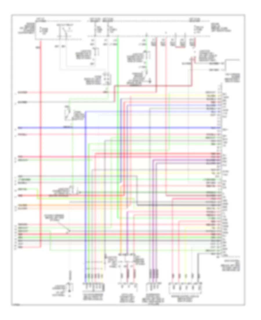
Anti-lock Brakes Wiring Diagram (3 of 3) for Lexus GX 470 2003
List of elements for Anti-lock Brakes Wiring Diagram (3 of 3) for Lexus GX 470 2003:
- (in dash harness, behind left end of dash)
- A15
- Acc cut relay
- Acc fuse 7.5a
- Ahco
- Brl
- D/g
- Data link connector 3 (below left side of dash)
- Diode (back-up light) (behind right side of dash)
- Dome fuse 10a
- Driver side j/b (behind lower left end of dash)
- E12
- Ecu-ig fuse 10a
- Eng+
- Eng-
- Engine control module (behind right end of dash)
- Engine room r/b (on left side of engine compartment)
- Ex1
- Exi4
- Flo
- Fro
- Gl1
- Gl2
- Gnd3
- Gnd4
- Gyaw
- Hard
- Hdcs
- Hot at all times
- Hot in on or accy
- Hot in on or start
- Ig1
- Ig1 fuse 2 10a
- Ind
- J/b 1 (behind center of dash)
- J18
- J20
- J28
- Junction conn 13 (at left kick panel)
- Junction connector (at left kick panel)
- Junction connector 1 (on left side of engine compt, near battery)
- Junction connector 19 (behind right end of dash)
- Junction connector 20 (behind right side of dash)
- Junction connector 24 (at front of center console)
- Nca
- Neo
- Park/ neutral position switch
- Parking brake switch (at base of brake lever assembly)
- Pkb
- Pnk
- Red
- Rl+
- Rl-
- Rr+
- Rr-
- Rss
- S10
- S20
- Sil
- Skid control ecu (behind left end of dash, above driver side j/b)
- Sp1
- Ss1+
- Ss1-
- Stp
- Suspension control ecu (behind left end of dash, near base of ``a" pillar)
- Trc+
- Trc-
- Vsc warning buzzer (behind right end of dash)
- Vscw
- Vys
- Yaw
- Yaw rate sensor (below front of center console)
- Yaw2
- Yss