ANTI-LOCK BRAKES
Anti-lock Brake Wiring Diagrams, with Traction Control for Lexus LS 400 1994

List of elements for Anti-lock Brake Wiring Diagrams, with Traction Control for Lexus LS 400 1994:
- A10
- A11
- A12
- A13
- A14
- A15
- A16
- A17
- A18
- A19
- A20
- A21
- A22
- A23
- A24
- A25
- A26
- Abs and traction ecu (behind glove box)
- Abs fusible link 60a
- Abs motor relay (right side of engine compt)
- Abs solenoid relay (right side of engine compt)
- Abso
- Alt
- Ast
- B10
- B11
- B12
- B13
- B14
- B15
- B16
- B17
- B18
- B19
- B20
- B21
- B22
- Bat
- D/g
- Data link connector 1 (top left side of engine)
- Data link connector 2 (right front side of engine compt)
- Ecu-b fuse 15a
- Ecu-ig fuse 15a
- Fl+
- Fl-
- Fr+
- Fr-
- Fss
- Fusible link box (left side of engine compt)
- G200 (left kick panel)
- G203 (right kick panel)
- Generator
- Gnd1
- Gnd2
- Hot at all times
- Hot in run
- J 3 srs junction connector (behind glove box)
- J/b 1 (left side of steering column)
- J/b 3 (behind i/p)
- J/b 4 (behind i/p)
- Lbl
- Left front abs speed sensor (behind left front wheel disk)
- Left rear abs speed sensor (behind left rear wheel disk)
- Mtt
- Pkb
- Pnk
- Red
- Right front abs speed sensor (behind right front wheel disk)
- Right rear abs speed sensor (behind right rear wheel disk)
- Rl+
- Rl-
- Rr+
- Rr-
- Rss
- Sac
- Sfl
- Sfr
- Smc
- Src
- Srl
- Srr
- Stop fuse 25a
- Stop light switch (mounted on brake pedal support)
- Stp
- Tmr
- Traction brake actuator (left side of engine compartment)
- Traction cut/ headlight cleaner switch
- Tsr
Anti-lock Brake Wiring Diagrams, with Traction Control (1 of 2) for Lexus LS 400 1994
List of elements for Anti-lock Brake Wiring Diagrams, with Traction Control (1 of 2) for Lexus LS 400 1994:
- A10
- A11
- A12
- A13
- A14
- A15
- A16
- A17
- A18
- A19
- A20
- A21
- A22
- A23
- A24
- A25
- A26
- Abs and traction ecu (behind glove box)
- Abs fusible link 60a
- Abs motor relay (right side of engine compt)
- Abs solenoid relay (right side of engine compt)
- Abso
- Alt
- Ast
- B10
- B11
- B12
- B13
- B14
- B15
- B16
- B17
- B18
- B19
- B20
- B21
- B22
- Bat
- D/g
- Data link connector 1 (top left side of engine)
- Data link connector 2 (right front side of engine compt)
- Ecu-b fuse 15a
- Ecu-ig fuse 15a
- Fl+
- Fl-
- Fr+
- Fr-
- Fss
- Fusible link box (left side of engine compt)
- G200 (left kick panel)
- G203 (right kick panel)
- Generator
- Gnd1
- Gnd2
- Hot at all times
- Hot in run
- J 3 srs junction connector (behind glove box)
- J/b 1 (left side of steering column)
- J/b 3 (behind i/p)
- J/b 4 (behind i/p)
- Lbl
- Left front abs speed sensor (behind left front wheel disk)
- Left rear abs speed sensor (behind left rear wheel disk)
- Mtt
- Pkb
- Pnk
- Red
- Right front abs speed sensor (behind right front wheel disk)
- Right rear abs speed sensor (behind right rear wheel disk)
- Rl+
- Rl-
- Rr+
- Rr-
- Rss
- Sac
- Sfl
- Sfr
- Smc
- Src
- Srl
- Srr
- Stop fuse 25a
- Stop light switch (mounted on brake pedal support)
- Stp
- Tmr
- Traction brake actuator (left side of engine compartment)
- Traction cut/ headlight cleaner switch
- Tsr
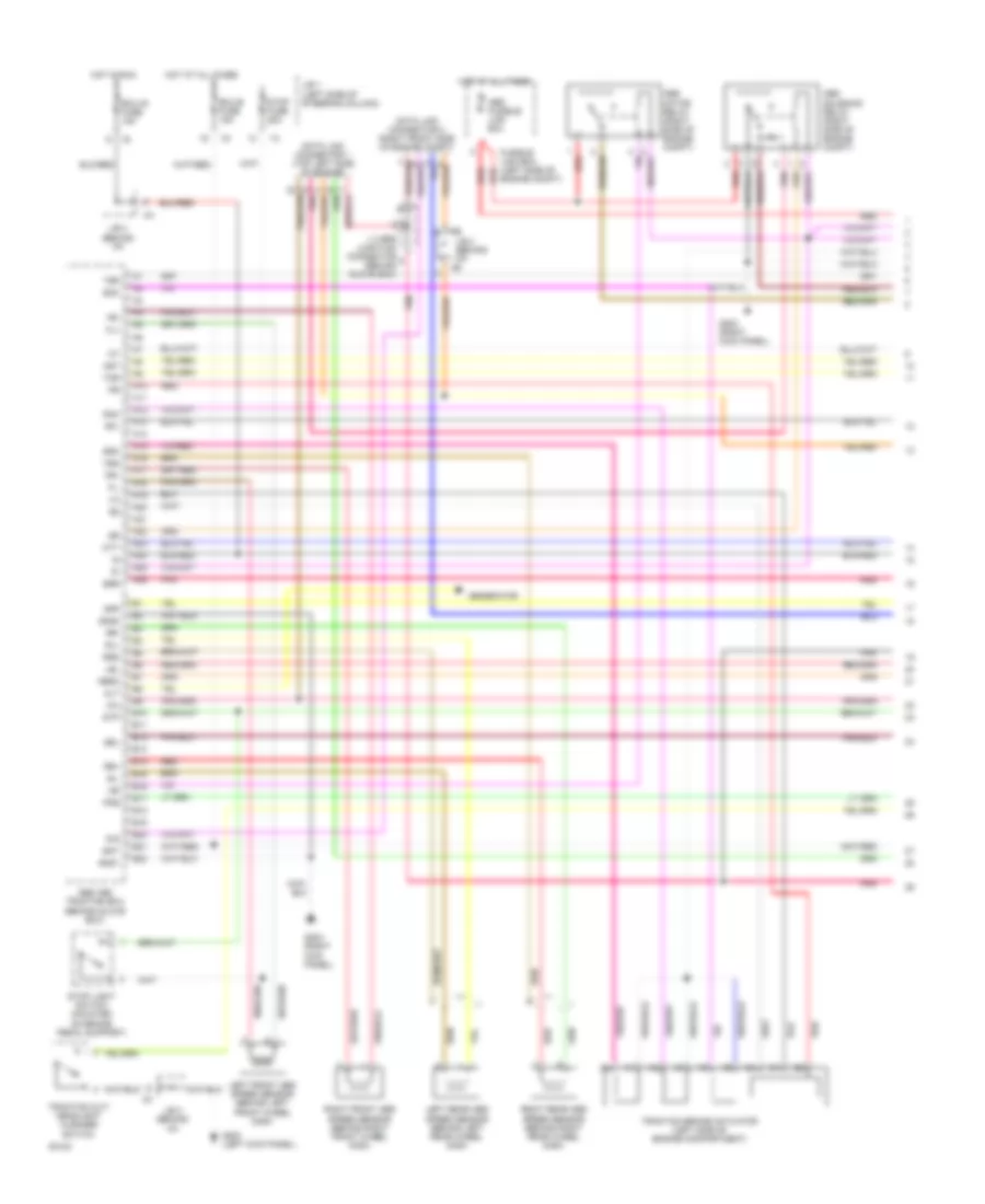
Anti-lock Brake Wiring Diagrams, with Traction Control (2 of 1) for Lexus LS 400 1994
List of elements for Anti-lock Brake Wiring Diagrams, with Traction Control (2 of 1) for Lexus LS 400 1994:
- 1b f5
- A/t indicator switch
- A10
- A11
- A12
- A13
- A14
- A15
- A16
- A17
- A18
- A19
- A20
- A21
- A22
- A23
- A24
- A25
- A26
- A27
- Abs
- Abs actuator (right side of engine compartment)
- Abs and traction ecu (behind glove box)
- Abso
- Acm
- B10
- B11
- B12
- B13
- B14
- B15
- B16
- B31
- B32
- Bat
- Bcm
- Brake fluid level switch (left rear of engine compartment)
- Brc
- Brfa
- Brp
- C10
- C11
- C12
- C13
- C14
- C15
- C16
- Combination meter
- Connector (behind glove box)
- Csw
- Engine control module (behind glove box)
- Flo
- Fro
- G114 (rear of left cylinder head)
- G203 (right kick panel)
- Gauge fuse 10a
- Gnd
- Hot at all times
- Hot in run
- Idl1
- Idl2
- Ig1
- Ind
- J/b 1 (left side of steering column)
- Nca
- Neo
- Parking brake switch (on parking brake support)
- Pkb
- Pnk
- Pnk b3
- Red
- Relay box 7 (right side of j/b #1)
- Rlo
- Rro
- Stp
- Sub throttle actuator (top right rear of engine)
- Thfa
- Tr2
- Tr5
- Trac
- Trac fuse 15a
- Trac off
- Traction control ecu (behind left side of i/p)
- Traction motor relay (left rear of engine compt)
- Traction pump and motor (left rear of engine compt)
- Traction solenoid relay (left front of engine compt)
- Trco
- Vsh
- Vth
- Vto1
- Vto2
- Warning and indicator light
- Wt/bu
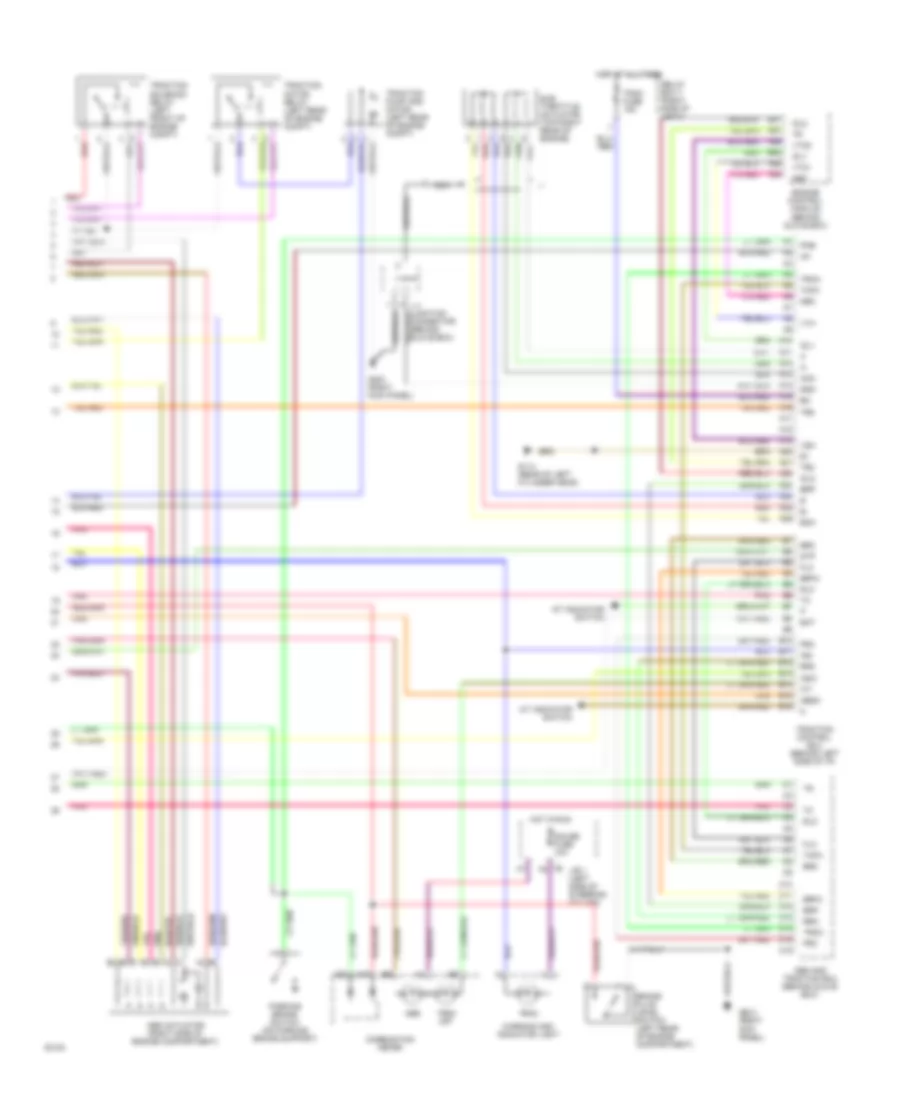
Anti-lock Brake Wiring Diagrams, with Traction Control (2 of 2) for Lexus LS 400 1994
List of elements for Anti-lock Brake Wiring Diagrams, with Traction Control (2 of 2) for Lexus LS 400 1994:
- 1b f5
- A/t indicator switch
- A10
- A11
- A12
- A13
- A14
- A15
- A16
- A17
- A18
- A19
- A20
- A21
- A22
- A23
- A24
- A25
- A26
- A27
- Abs
- Abs actuator (right side of engine compartment)
- Abs and traction ecu (behind glove box)
- Abso
- Acm
- B10
- B11
- B12
- B13
- B14
- B15
- B16
- B31
- B32
- Bat
- Bcm
- Brake fluid level switch (left rear of engine compartment)
- Brc
- Brfa
- Brp
- C10
- C11
- C12
- C13
- C14
- C15
- C16
- Combination meter
- Connector (behind glove box)
- Csw
- Engine control module (behind glove box)
- Flo
- Fro
- G114 (rear of left cylinder head)
- G203 (right kick panel)
- Gauge fuse 10a
- Gnd
- Hot at all times
- Hot in run
- Idl1
- Idl2
- Ig1
- Ind
- J/b 1 (left side of steering column)
- Nca
- Neo
- Parking brake switch (on parking brake support)
- Pkb
- Pnk
- Pnk b3
- Red
- Relay box 7 (right side of j/b #1)
- Rlo
- Rro
- Stp
- Sub throttle actuator (top right rear of engine)
- Thfa
- Tr2
- Tr5
- Trac
- Trac fuse 15a
- Trac off
- Traction control ecu (behind left side of i/p)
- Traction motor relay (left rear of engine compt)
- Traction pump and motor (left rear of engine compt)
- Traction solenoid relay (left front of engine compt)
- Trco
- Vsh
- Vth
- Vto1
- Vto2
- Warning and indicator light
- Wt/bu
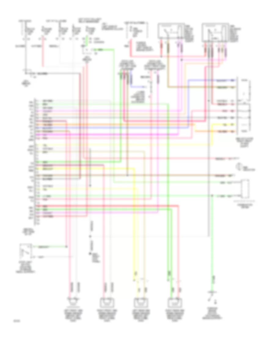
Anti-lock Brake Wiring Diagrams, without Traction Control for Lexus LS 400 1994
List of elements for Anti-lock Brake Wiring Diagrams, without Traction Control for Lexus LS 400 1994:
- (canada)
- (usa)
- A12
- A20
- Abs actuator (right front of eng compt)
- Abs ecu (left side of i/p)
- Abs fusible link 60a
- Abs indicator
- Abs motor relay (right side of engine compt)
- Abs solenoid relay (right side of engine compt)
- Ast
- Bat
- Combination meter
- D/g
- Data link connector 1 (top left side of engine)
- Data link connector 2 (right front side of engine compt)
- Ecu-b fuse 15a
- Ecu-ig fuse 15a
- Fl+
- Fl-
- Fr+
- Fr-
- Fss
- Fusible link box (left side of engine compt)
- G203 (right kick panel)
- Gauge fuse 10a
- Gnd1
- Gnd2
- Hot at all times
- Hot in run
- Hot with taillight relay energized
- J 3 srs junction connector (behind glove box)
- J/b 1 (left side of steering column)
- J/b 3 (behind i/p)
- J/b 4 (behind i/p)
- Left front abs speed sensor (behind left front wheel disk)
- Left rear abs speed sensor (behind left rear wheel disk)
- Panel fuse 7.5a
- Parking brake switch (on parking brake support)
- Pkb
- Pnk
- Red
- Ree
- Right front abs speed sensor (behind right front wheel disk)
- Right rear abs speed sensor (behind right rear wheel disk)
- Rl+
- Rl-
- Rr+
- Rr-
- Sfl
- Sfr
- Srr
- Stop fuse 25a
- Stop light switch (mounted on brake pedal support)
- Stp