ANTI-LOCK BRAKES
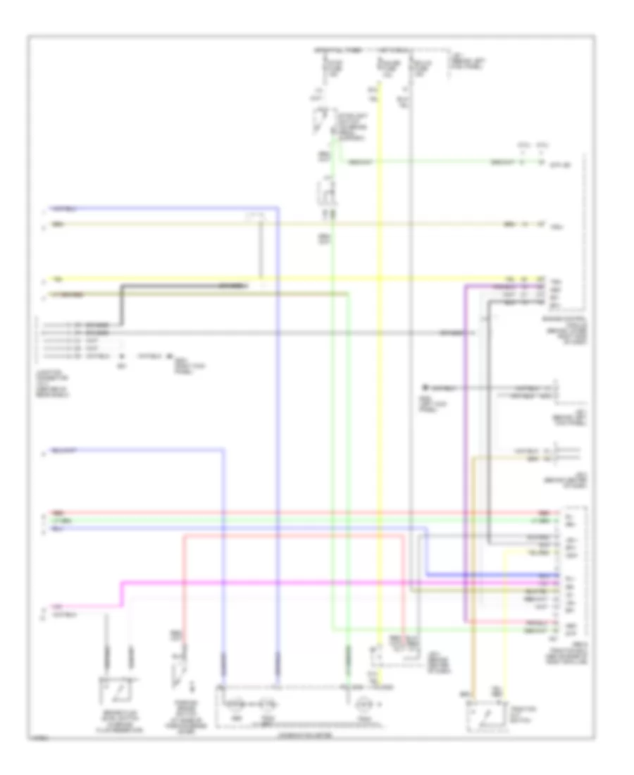
Anti-lock Brake Wiring Diagrams, with Traction Control (1 of 2) for Lexus SC 400 1998

List of elements for Anti-lock Brake Wiring Diagrams, with Traction Control (1 of 2) for Lexus SC 400 1998:
- (behind left side of dash) data link connector 2
- (dash harn, right end of dash)
- (dash harn, right side of dash)
- (front of left front fender) g100
- A20
- A22
- A4/12 pnk
- Abs 1 fusible link 60a
- Abs actuator (at right rear corner of engine compt)
- Abs and traction ecu (above base of right b-pillar)
- Abs motor relay
- Abs sol relay
- Ast
- B21
- Braided
- D/g
- Data link connector 1 (3.0l: on left side of engine, near strut tower) (4.0l: at left rear side of engine)
- E8 (eng room harness, left fender apron)
- Fl+
- Fl-
- Fr+
- Fr-
- Fuse block (at left side of engine compt, behind battery)
- G101 (front side of right fender)
- G203 (right kick panel)
- Gnd1
- Gnd2
- Gnd3
- Gnd4
- H13
- Hot at all times
- I17
- I20
- Ind
- Instrument cluster system
- Junction block 3 (behind center of dash) h12
- Junction connector j/c 2 (center of rear shelf)
- Left front abs speed sensor (left front wheel assembly)
- Left rear abs speed sensor (left rear wheel assembly)
- Pnk
- R/b 6 (on left side of engine compartment, behind strut tower)
- Red
- Right front abs speed sensor (right front wheel assembly)
- Right rear abs speed sensor (right rear wheel assembly)
- Sflh
- Sflr
- Sfrh
- Sfrr
- Smc
- Spc
- Spd
- Src
- Srlh
- Srlr
- Srrh
- Srrr
- Trc+
- Trc-
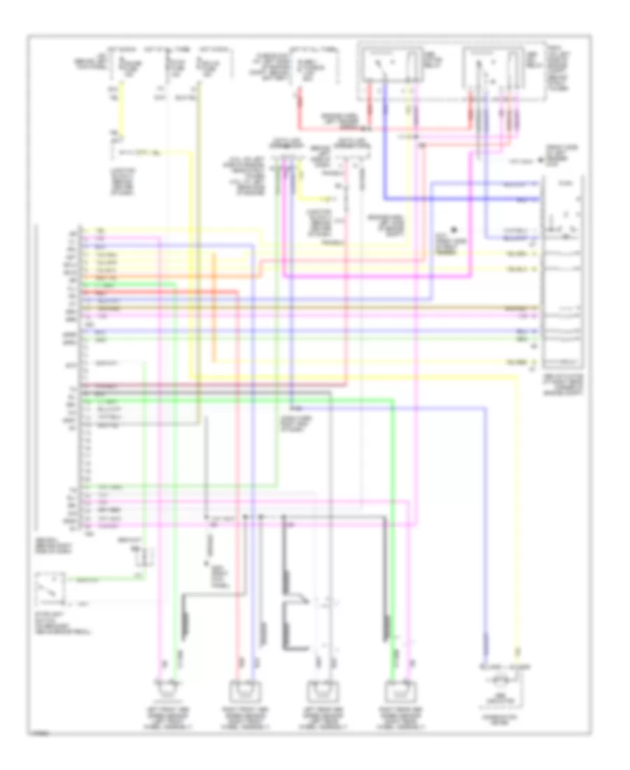
Anti-lock Brake Wiring Diagrams, with Traction Control (2 of 2) for Lexus SC 400 1998
List of elements for Anti-lock Brake Wiring Diagrams, with Traction Control (2 of 2) for Lexus SC 400 1998:
- (3.0l)
- (4.0l)
- A21
- Abs
- Abs & traction ecu (above base of right b-pillar)
- B21
- Braided
- Brake fluid level switch (in brake fluid reservoir)
- C10
- C12
- C25
- Combination meter
- Csw
- D13
- E12
- E18
- E20
- Ecu-ig fuse 15a
- Efi+
- Efi-
- Engine control module (behind lower right side of dash)
- G200 (left kick panel)
- G203 (right kick panel)
- Gauge fuse 10a
- Hot at all times
- Hot in run
- I10
- Ig1
- J/b 1 (behind left kick panel)
- J/b 3 (behind center of dash)
- Junction connector j/c 2 (center of rear shelf)
- Lbl+
- Lbl-
- Neo
- Parking brake switch (at base of parking brake lever)
- Red
- Rl+
- Rl-
- Rr+
- Rr-
- Stop fuse 15a
- Stoplight switch (on brake pedal support)
- Stp
- Stp, bk
- Trac
- Trac off
- Traction cut switch
- Trc+
- Trc-
Anti-lock Brake Wiring Diagrams, without Traction Control for Lexus SC 400 1998
List of elements for Anti-lock Brake Wiring Diagrams, without Traction Control for Lexus SC 400 1998:
- (3.0l: on left side of engine, near strut tower) (4.0l: at left rear side of engine)
- (behind left side of dash)
- (dash harn, right end of dash)
- (engine harn, left fender apron)
- (engine harn, left side of engine compt)
- (front side of left fender) g100
- (on left side of engine compt, behind strut tower)
- A23
- A24
- Abs 1 fusible link 60a
- Abs actuator (at right rear corner of engine compt)
- Abs ecu (behind right side of dash)
- Abs indicator
- Abs motor relay
- Abs sol relay
- Ast
- Braided
- C12
- C25
- Combination meter
- D/g
- D13
- Data link connector 1
- Data link connector 2
- E12
- E20
- Ecu-ig fuse 15a
- Fl+
- Fl-
- Fr+
- Fr-
- Fuse block (at left side of engine compt, behind battery)
- G101 (front side of right fender)
- G203 (right kick panel)
- Gauge fuse 15a
- Gnd1
- Gnd2
- H12
- H13
- Hot at all times
- Hot in run
- I10
- I20
- I24
- Ig1
- J/b 1 (behind left kick panel)
- Junction block 3 (behind center of dash)
- Left front abs speed sensor (left front wheel assembly)
- Left rear abs speed sensor (left rear wheel assembly)
- R/b 6
- Red
- Right front abs speed sensor (right front wheel assembly)
- Right rear abs speed sensor (right rear wheel assembly)
- Rl+
- Rl-
- Rr+
- Rr-
- Sflh
- Sflr
- Sfrh
- Sfrr
- Srh
- Srr
- Stop fuse 15a
- Stoplight switch (on bracket, above brake pedal)
- Stp