ANTI-LOCK BRAKES
Anti-lock Brakes Wiring Diagram, with Stability Assist for Lincoln LS 2005

List of elements for Anti-lock Brakes Wiring Diagram, with Stability Assist for Lincoln LS 2005:
- (in dash panel to headlamp junction harness, near breakout to right front wheel speed sensor) s101
- (in dash pnl to headlamp junction harness, near breakout to left front wheel speed sensor)
- 10-cc17
- 10-cf51
- 20-cf6a
- 29s-cf1
- 29s-cf2
- 29s-dk30
- 29s-re13
- 30-cf13
- 30-cf6a
- 31-cf6a
- 31-cf6b
- 31s-cf45
- 4-cf6
- 4-cf66
- 5-cf6
- 5-cf66
- 7-cc1
- 7-cf32
- 7-cf34
- 7-cf38
- 7-cf40
- 7-cf64
- 7-cf65
- 8-cc18
- 8-cf32
- 8-cf34
- 8-cf38
- 8-cf40
- 8-cf51
- 8-cf54
- 8-cf63
- 8-cf64
- 8-cf65
- 8-cf68
- 8-gn14
- 9-cc1
- 9-cf51
- 9-cf64
- 9-cf65
- 9-cf68
- Abs control module (right front side of engine compartment)
- Abs ind lamp
- Abs test connector (in left
- Auxiliary junction box (ajb) (interior) (under left side of dash)
- Auxiliary junction box (ajb) (underhood) (in right front of engine compartment)
- Bpfs nc
- Bpfs no
- Bpfs sta
- Brake booster sensor (in left rear of engine compt)
- Brake pedal position sensor (at left shock tower)
- Brake pedal position switch (on top of brake pedal support)
- C175a
- C220b
- C270a
- C270c
- C270d
- C283c
- C283d
- C4014b
- C420b
- Can2+
- Can2-
- Central junction box (cjb) (behind right kick panel)
- Fuse 30a
- Fuse 40a
- Fuse 5a
- G101 (on right radiator support)
- G202 (on bottom of left side ``a" pillar)
- G302 (below left front seat)
- Gnd
- Ground
- Hot at all times
- Hot in run
- Hot in start or run
- Illum
- Ind
- Instrument cluster
- Interior lights system
- J/c 4 (behind left side of dash)
- Left front wheel speed sensor (on left front wheel assembly, on spindle assembly)
- Left rear wheel speed sensor (on left rear wheel assembly, on brake knuckle)
- Navigation module (on package tray)
- On/off
- Parking aid module (pam) (on left rear of package tray)
- Powertrain control module (pcm) (right rear of engine compt)
- Primary brake pressure sensor (in left rear of engine compt)
- Pwr
- Rear electronic module (rem) (in right side of luggage compt)
- Rear of engine compt)
- Red
- Right front wheel speed sensor (on right front wheel assembly, on spindle assembly)
- Right rear wheel speed sensor (on right rear wheel assembly, on brake knuckle)
- S122
- S140
- S146
- S211
- S320
- Scp+
- Scp-
- Sig rtn
- Steering position sensor (on steering column)
- Traction control switch
- Vbatt
- Vpwr
- Vref
- Vss
- Yaw velocity sensor (on center of floor pan)
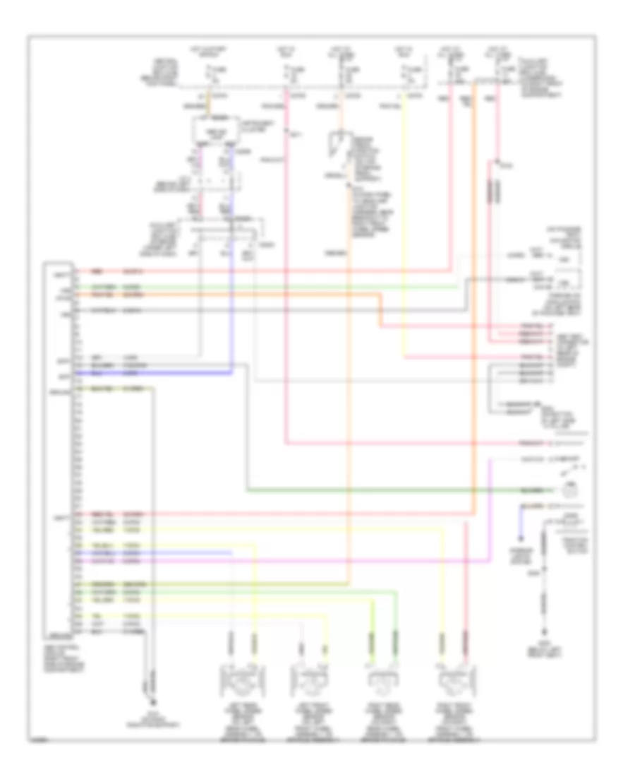
Anti-lock Brakes Wiring Diagram, without Stability Assist for Lincoln LS 2005
List of elements for Anti-lock Brakes Wiring Diagram, without Stability Assist for Lincoln LS 2005:
- (on package tray) navigation module
- 20-cf6a
- 29s-cf58
- 30-cf13
- 30-cf6a
- 31-cf6a
- 31-cf6b
- 31s-cf45
- 4-cf6
- 5-cf6
- 7-cf32
- 7-cf34
- 7-cf38
- 7-cf40
- 8-cf32
- 8-cf34
- 8-cf38
- 8-cf40
- 8-cf54
- 8-cf63
- 8-gn14
- Abs control module (right front side of engine compartment)
- Abs ind lamp
- Abs test connector (in left
- Auxiliary junction box (ajb) (interior) (under left side of dash)
- Auxiliary junction box (ajb) (underhood) (in right front of engine compartment)
- Brake pedal position switch (on top of brake pedal support)
- C220b
- C270a
- C270c
- C270d
- C283c
- C283d
- C4014b
- Central junction box (cjb) (behind right kick panel)
- Fuse 30a
- Fuse 40a
- Fuse 5a
- G101 (on right radiator support)
- G202 (on bottom of left side ``a" pillar)
- G302 (below left front seat)
- Ground
- Hot at all times
- Hot in run
- Hot in start or run
- Illum
- Ind
- Instrument cluster
- Interior lights system
- J/c 4 (behind left side of dash)
- Left front wheel speed sensor (on left front wheel assembly, on spindle assembly)
- Left rear wheel speed sensor (on left rear wheel assembly, on brake knuckle)
- On/off
- Parking aid module (pam) (on left rear of package tray)
- Rear of engine compt)
- Red
- Right front wheel speed sensor (on right front wheel assembly, on spindle assembly)
- Right rear wheel speed sensor (on right rear wheel assembly, on brake knuckle)
- S101 (in dash panel to headlamp junction harness, near breakout to right front wheel speed sensor)
- S122
- S211
- S320
- Scp+
- Scp-
- Traction control switch
- Vbatt
- Vpwr
- Vss