ENGINE PERFORMANCE
3.0L
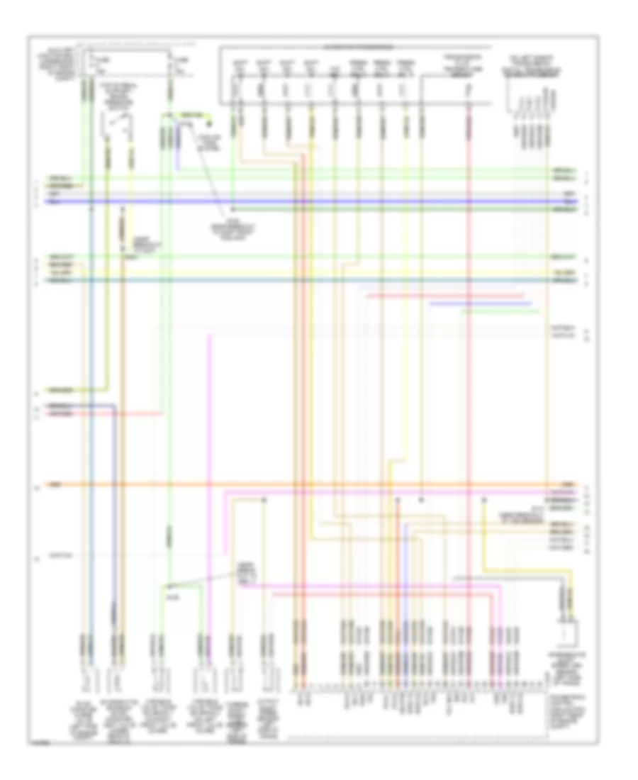
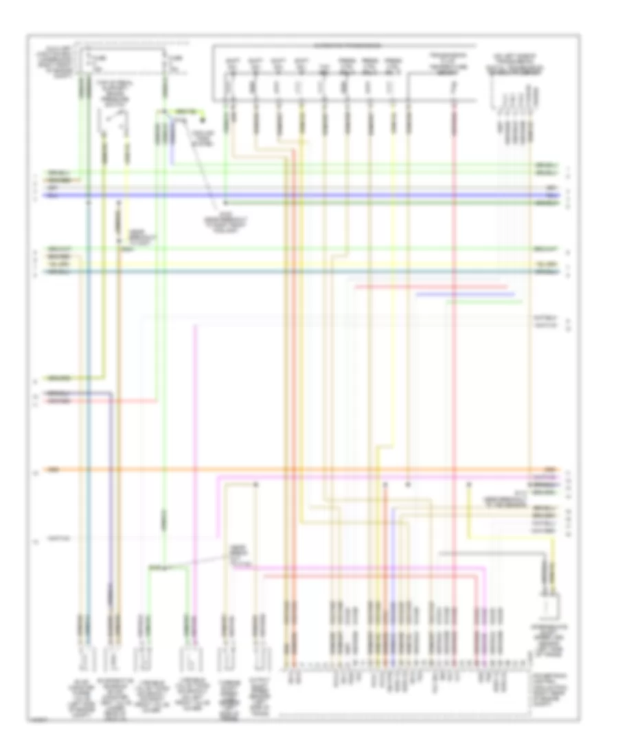
3.0L, Engine Performance Wiring Diagram (1 of 4) for Lincoln LS 2004

List of elements for 3.0L, Engine Performance Wiring Diagram (1 of 4) for Lincoln LS 2004:
- (in breakout to battery junction box) s403
- (left radiator support) g101
- (near break- out to c291)
- (near break- out to underhood aux junction box)
- (near breakout to ambient air temp sensor)
- (near breakout to right front wheel sensor)
- (right front fender) g102
- 15s-re21
- 15s-re25
- 15s-re8
- 29-re8
- 29s-re13
- 31-re21
- 31-re25
- 31-re26
- 31-re8
- 31s-pg24
- 4-ec7
- 4-re8
- 5-ec7
- 5-re8
- 7-pg24
- 7-re14
- 7-re8
- 7-rj30
- 7-rj35
- 8-fa88
- 8-pa47
- 8-re32
- 8-rj10
- 8-rj13
- 8-rj17
- 8-rj22
- 8-rj30
- 8-rj35
- 8-rj36
- 8-ta21
- 8-ta67
- 8-ta68
- 9-re8
- 9-rj22
- 9-rj30
- 91-re27
- 91s-fa79
- 91s-rl25
- 91s-rl3
- A/c pressure transducer sensor (left front of engine compt)
- A/c system (a/c clutch relay)
- Ac clutch
- Ac press
- Auxiliary junction box (underhood) (right front of engine compt)
- Battery junction box (in luggage compt, near battery)
- Brake in
- C175b
- C270b
- C270c
- C270d
- Can +
- Can -
- Central junction box (behind right kick panel)
- Cooling fans system
- Cops & heated oxygen sensor relay
- Cruise control system (steering wheel speed control switches)
- Data link connector (under left side of dash)
- Electronic throttle control module (behind left side of dash)
- Etc ref
- Etc sig
- Etc sig rtn
- Etc signal
- Evap ctrl
- Evap purge
- Fan ctrl
- Fuel pump motor diode
- Fuel tank pressure transducer sensor (under rear of vehicle)
- Fuse 30a
- Fuse 5a
- G102 (right front fender)
- Ground
- Hot at all times
- Hot in run or start
- Iat sens
- Inertia fuel shutoff (ifs) switch (left kick panel)
- Maf rtn
- Maf sig
- Man mode (+)
- Man mode (-)
- Mass airflow (maf) sensor (on air intake assembly)
- Mt sw +
- Mt sw -
- O/d cancel sw
- Od off
- Pcm power diode
- Pcm power relay
- Power
- Powertrain control module (pcm) (right rear of engine compt)
- Prg sig
- Red
- Ref volt
- Rem sig
- Rest mod
- S102
- S103
- S111
- S112
- S113
- S138 (near breakout to auxiliary junction box)
- S211
- S220
- S328 (near breakout to yaw velocity sensor)
- Scp +
- Scp -
- Signal rtn
- Spd sw
- Tank press
- Transmission shift selector (a/t)
- Voltage
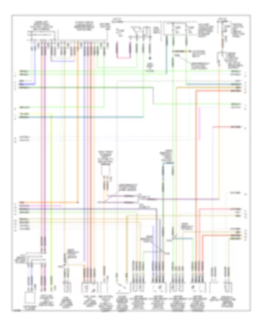
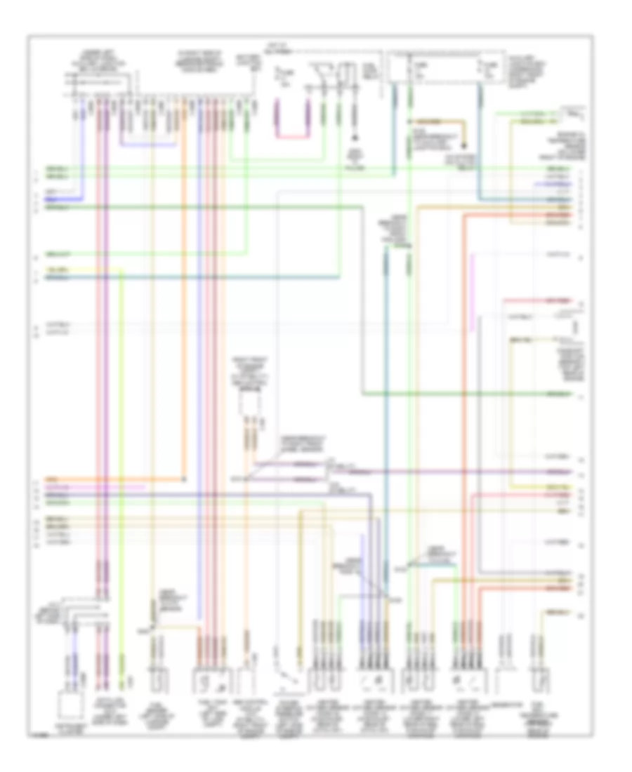
3.0L, Engine Performance Wiring Diagram (2 of 4) for Lincoln LS 2004
List of elements for 3.0L, Engine Performance Wiring Diagram (2 of 4) for Lincoln LS 2004:
- (near break- out to imrc 1)
- (near breakout to c237)
- (on left side of transmission) digital transmission range (dtr) sensor
- (top of pedal support) brake pressure switch
- 8-rj25
- 8-rj26
- 8-ta26
- 8-ta27
- 8-ta37
- 8-ta38
- 8-ta39
- 8-ta40
- 8-ta51
- 8-ta74
- 9-ta1
- 91s-rj25
- 91s-rj26
- 91s-ta23
- 91s-ta24
- 91s-ta47
- 91s-ta63
- 91s-ta64
- 91s-ta65
- 91s-ta69
- 91s-ta70
- Automatic transmission
- Auxiliary junction box (underhood) (right front of engine compt)
- C175t
- Cooling fans system
- Evap canister purge valve (left side of engine compt)
- Evaporative emission (evap) canister vent valve (under rear of vehicle)
- Fuse 15a
- H2os 12
- H2os 22
- Intermediate shaft speed (iss) sensor (left side of trans)
- Iss
- Oss
- Output shaft speed sensor (left side of trans)
- P,2,1
- P,n,1
- P,r,2
- P,r,n,3/4
- Pcs a
- Pcs b
- Pcs c
- Power
- Powertrain control module (pcm) (right rear of engine compt)
- Press ctrl sol a
- Press ctrl sol b
- Press ctrl sol c
- S105 (near breakout to right front foglamp)
- S110 (near breakout to tss sensor)
- S125
- S204
- Shift sol a
- Shift sol b
- Shift sol c
- Shift sol d
- Sig rtn
- Ss a
- Ss b
- Ss c
- Ss d
- Tcc sol
- Tft
- Tr1
- Tr2
- Tr3a
- Tr4
- Transmission fluid temperature sensor
- Tss
- Turbine shaft speed (tss) sensor (left side of trans)
- Variable valve timing solenoid 1 (on right front valve cover)
- Variable valve timing solenoid 2 (on left front valve cover)
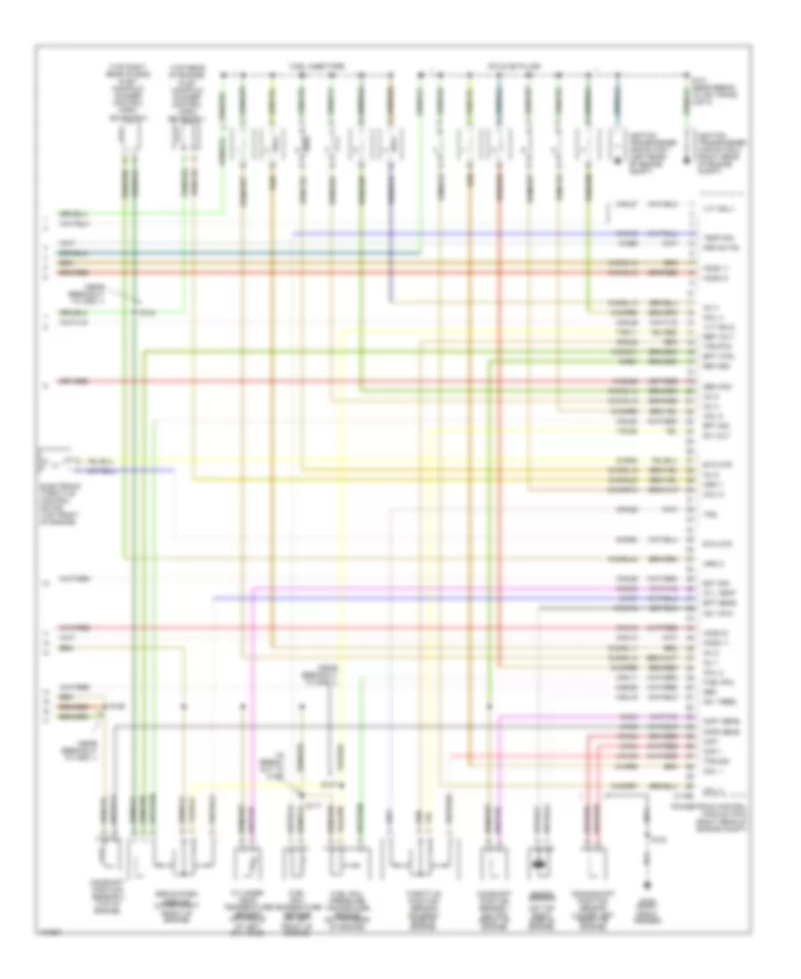
3.0L, Engine Performance Wiring Diagram (3 of 4) for Lincoln LS 2004
List of elements for 3.0L, Engine Performance Wiring Diagram (3 of 4) for Lincoln LS 2004:
- (in right side of luggage compt) rear electronic module (rem)
- (near breakout ho2s 12)
- (near breakout to auxiliary junction box)
- (near breakout to ftp sensor)
- (near breakout to imrc 2)
- (near breakout to right front foglamp) s106
- (near breakout to right front wheel sensor)
- (right front of engine compt) (w/ stability) abs control module
- (under left side of dash) auxiliary junction box (interior)
- A/c system (a/c clutch relay)
- Abs control module (w/o stability) (right front of engine compt)
- Auxiliary junction box (underhood) (right front of engine compt)
- Battery junction box
- Brake pedal position switch (on top of brake pedal support)
- C155
- C220b
- C251
- C270d
- C283b
- C283c
- C283d
- C420a
- C420b
- C420c
- C420d
- Central junction box (behind right kick panel)
- Data link connector (dlc) (under left side of dash)
- Engine oil temperature sensor (left side of engine)
- Fuel pump relay
- Fuel sender (left side of luggage compt)
- Fuel tank unit (left side of luggage compt)
- Fuse 15a
- Fuse 5a
- G300 (right "c" pillar)
- Gen- erator
- Heated oxygen sensor (ho2s) 11 (lower right rear of eng, in exhaust manifold)
- Heated oxygen sensor (ho2s) 12 (in exhaust, rear of catalyst)
- Heated oxygen sensor (ho2s) 21 (lower left rear of eng, in exhaust manifold)
- Heated oxygen sensor (ho2s) 22 (in exhaust, rear of catalyst)
- Hot at all times
- Instrument cluster
- J/c 4 (behind left side of dash)
- Nca
- Power steering pressure switch (left side of engine compt)
- S101
- S109
- S132
- S135
- S402
- W/ stability
- W/o stability
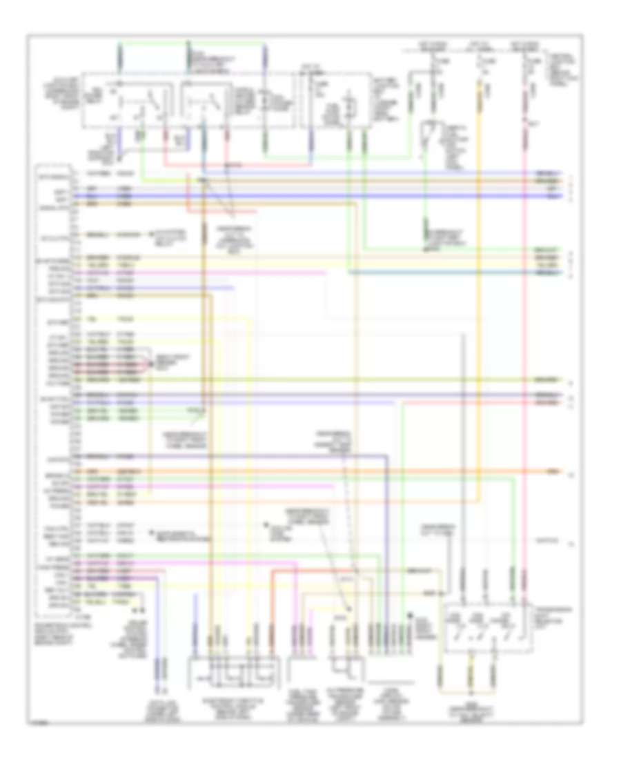
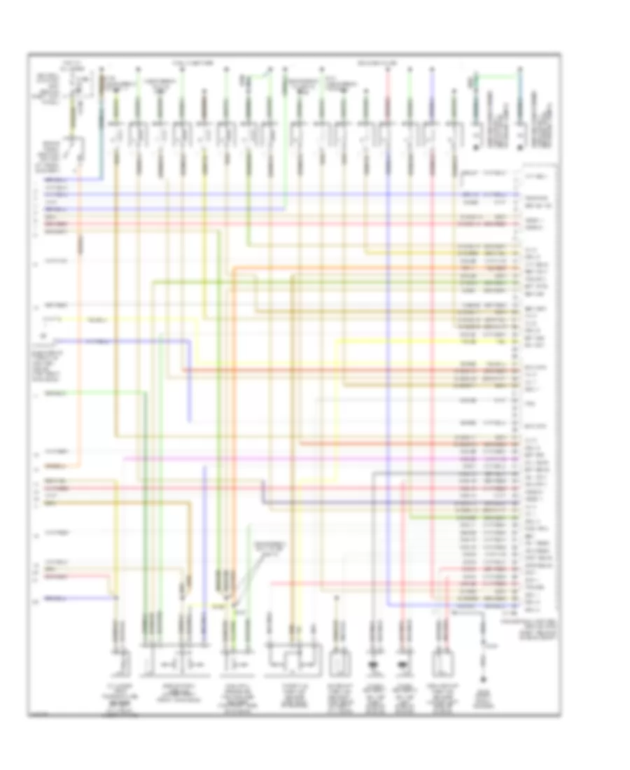
3.0L, Engine Performance Wiring Diagram (4 of 4) for Lincoln LS 2004
List of elements for 3.0L, Engine Performance Wiring Diagram (4 of 4) for Lincoln LS 2004:
- (in break- out to c192)
- (near breakout to imrc 1)
- (on top right side of engine)
- (top rear of engine) inlet manifold runner control (imrc) solenoid 1
- (top right rear of eng) inlet manifold runner control (imrc) solenoid 2
- 10-ba25
- 10-rj18
- 10-rj4
- 32-rg3
- 33-rg3
- 7-rj28
- 7-rn11
- 8-ba25
- 8-ce6
- 8-rj11
- 8-rj12
- 8-rj14
- 8-rj15
- 8-rj18
- 8-rj2
- 8-rj20
- 8-rj26
- 8-rj28
- 8-rj3
- 8-rj33
- 8-rj39
- 8-rj4
- 8-rj7
- 8-rl26
- 8-rl27
- 9-re1
- 9-rj28
- 91-rr5
- 91s-rj14
- 91s-rj15
- 91s-rl10
- 91s-rl11
- 91s-rl12
- 91s-rl13
- 91s-rl14
- 91s-rl15
- 91s-rl20
- 91s-rl40
- 91s-rl7
- 91s-rr10
- 91s-rr6
- 91s-rr7
- 91s-rr8
- 91s-rr9
- C175e
- Camshaft position sensor 1 (on top front of engine)
- Camshaft position sensor 2 (top of engine)
- Ckp +
- Ckp -
- Cmp1 sens
- Cmp2 sens
- Coil 1
- Coil 2
- Coil 3
- Coil 4
- Coil 5
- Coil 6
- Coils on plugs
- Crankshaft position sensor (lower left front of engine)
- Cyl temp
- Cylinder head temperature sensor (on middle of left cyl head)
- Dc volt
- Egr system module (upper right front of engine)
- Electronic throttle control motor (top front of engine)
- Eot sig
- Ept ctrl
- Ept sens
- Ept sig
- Etc mtr
- Fuel injectors
- Fuel rail
- Fuel rail pressure transducer sensor (on top rear of engine)
- Fuel rail temperature sensor (on left front of engine)
- G102 (right front fender)
- Gen
- Gen com
- Ho2s 11
- Ho2s 21
- Ignition transformer capacitor 1 (left rear of engine compt)
- Ignition transformer capacitor 2 (right rear of engine compt)
- Imrc 1
- Imrc 2
- Inj 1
- Inj 2
- Inj 3
- Inj 4
- Inj 5
- Inj 6
- Knock sensor
- Ks 1 feed
- Ks 1 rtn
- Nca
- Powertrain control module (pcm) (right rear of engine compt)
- Psp sw fd
- Ref volt
- Return
- S117
- S124
- S126
- S127
- S131 (near break to ign trans cap 2)
- S134
- Temp sig
- Throttle position sensor (on right side of engine)
- Tps
- Tps rtn
- Tps sig
- Vvt sol1
- Vvt sol2
3.9L
3.9L, Engine Performance Wiring Diagram (1 of 4) for Lincoln LS 2004
List of elements for 3.9L, Engine Performance Wiring Diagram (1 of 4) for Lincoln LS 2004:
- (in breakout to battery junction box) s403
- (left radiator support) g101
- (near break- out to ambient temp sensor)
- (near break- out to c291)
- (near break- out to underhood aux junction box)
- (near breakout to right front wheel sensor)
- (right front fender) g102
- 15s-re21
- 15s-re25
- 15s-re8
- 29-re8
- 29s-re13
- 31-re21
- 31-re25
- 31-re26
- 31-re8
- 31s-pg24
- 4-ec7
- 4-re8
- 5-ec7
- 5-re8
- 7-pg24
- 7-re14
- 7-re8
- 7-rj30
- 7-rj35
- 8-fa88
- 8-pa47
- 8-re32
- 8-rj10
- 8-rj13
- 8-rj17
- 8-rj22
- 8-rj30
- 8-rj35
- 8-rj36
- 8-ta21
- 8-ta67
- 8-ta68
- 9-re8
- 9-rj22
- 9-rj30
- 91-re27
- 91s-fa79
- 91s-rl25
- 91s-rl3
- A/c pressure transducer sensor (left front of engine compt)
- A/c system (a/c clutch relay)
- Ac clutch
- Ac press
- Auxiliary junction box (underhood) (right front of engine compt)
- Battery junction box (in luggage compt, near battery)
- Brake in
- C175b
- C270b
- C270c
- C270d
- Can +
- Can -
- Central junction box (behind right kick panel)
- Cooling fans system
- Cops & heated oxygen sensor relay
- Cruise control system (steering wheel speed control switches)
- Data link connector (under left side of dash)
- Electronic throttle control module (behind left side of dash)
- Etc ref
- Etc sig
- Etc sig rtn
- Etc signal
- Evap ctrl
- Evap purge
- Fan ctrl
- Fuel pump motor diode
- Fuel tank pressure transducer sensor (under rear of vehicle)
- Fuse 30a
- Fuse 5a
- G102 (right front fender)
- Ground
- Hot at all times
- Hot in run or start
- Iat sens
- Inertia fuel shutoff (ifs) switch (left kick panel)
- Maf rtn
- Maf sig
- Man mode (+)
- Man mode (-)
- Mass airflow (maf) sensor (on air intake assembly)
- Mt sw +
- Mt sw -
- O/d cancel sw
- Od off
- Pcm power diode
- Pcm power relay
- Power
- Powertrain control module (pcm) (right rear of engine compt)
- Prg sig
- Red
- Ref volt
- Rem sig
- Rest mod
- S102
- S103
- S111
- S112
- S113
- S138 (near breakout to auxiliary junction box)
- S211
- S220
- S328 (near breakout to yaw velocity sensor)
- Scp +
- Scp -
- Signal rtn
- Spd sw
- Tank press
- Transmission shift selector (a/t)
- Voltage
3.9L, Engine Performance Wiring Diagram (2 of 4) for Lincoln LS 2004
List of elements for 3.9L, Engine Performance Wiring Diagram (2 of 4) for Lincoln LS 2004:
- (near break- out to c140)
- (near breakout to c237)
- (on left side of transmission) digital transmission range (dtr) sensor
- (top of pedal support) brake pressure switch
- 8-rj25
- 8-rj26
- 8-ta26
- 8-ta27
- 8-ta37
- 8-ta38
- 8-ta39
- 8-ta40
- 8-ta51
- 8-ta74
- 9-ta1
- 91s-rj25
- 91s-rj26
- 91s-ta23
- 91s-ta24
- 91s-ta47
- 91s-ta63
- 91s-ta64
- 91s-ta65
- 91s-ta69
- 91s-ta70
- Automatic transmission
- Auxiliary junction box (underhood) (right front of engine compt)
- C175t
- Cooling fans system
- Evap canister purge valve (left side of engine compt)
- Evaporative emission (evap) canister vent valve (under rear of vehicle)
- Fuse 15a
- H2os 12
- H2os 22
- Intermediate shaft speed (iss) sensor (left side of trans)
- Iss
- Oss
- Output shaft speed sensor (left side of trans)
- P,2,1
- P,n,1
- P,r,2
- P,r,n,3/4
- Pcs a
- Pcs b
- Pcs c
- Power
- Powertrain control module (pcm) (right rear of engine compt)
- Press ctrl sol a
- Press ctrl sol b
- Press ctrl sol c
- S105 (near breakout to right front foglamp)
- S110 (near breakout to tss sensor)
- S125
- S204
- Shift sol a
- Shift sol b
- Shift sol c
- Shift sol d
- Sig rtn
- Ss a
- Ss b
- Ss c
- Ss d
- Tcc sol
- Tft
- Tr1
- Tr2
- Tr3a
- Tr4
- Transmission fluid temperature sensor
- Tss
- Turbine shaft speed (tss) sensor (left side of trans)
- Variable valve timing solenoid 1 (on right front valve cover)
- Variable valve timing solenoid 2 (on left front valve cover)
3.9L, Engine Performance Wiring Diagram (3 of 4) for Lincoln LS 2004
List of elements for 3.9L, Engine Performance Wiring Diagram (3 of 4) for Lincoln LS 2004:
- (in right side of luggage compt) rear electronic module (rem)
- (near breakout ho2s 12)
- (near breakout to c140)
- (near breakout to ftp sensor)
- (near breakout to right front foglamp) s106
- (near breakout to right front wheel sensor)
- (right front of engine compt) (w/ stability) abs control module
- (under left side of dash) auxiliary junction box (interior)
- A/c system (a/c clutch relay)
- Abs control module (w/o stability) (right front of engine compt)
- Auxiliary junction box (underhood) (right front of engine compt)
- Battery junction box
- C155
- C220b
- C251
- C283b
- C283c
- C283d
- C420a
- C420b
- C420c
- C420d
- Camshaft position sensor 2 (top left rear of engine)
- Data link connector (dlc) (under left side of dash)
- Engine oil temperature sensor (on lower front of engine)
- Fuel pump relay
- Fuel rail temperature sensor (top right rear of engine)
- Fuel sender (left side of luggage compt)
- Fuel tank unit (left side of lugg compt)
- Fuse 10a
- Fuse 15a
- G300 (right "c" pillar)
- Generator
- Heated oxygen sensor (ho2s) 11 (lower right rear of eng, in exhaust manifold)
- Heated oxygen sensor (ho2s) 12 (in exhaust, rear of catalyst)
- Heated oxygen sensor (ho2s) 21 (lower left rear of eng, in exhaust manifold)
- Heated oxygen sensor (ho2s) 22 (in exhaust, rear of catalyst)
- Hot at all times
- Instrument cluster
- J/c 4 (behind left side of dash)
- Nca
- Power steering pressure switch (left side of engine compt)
- S101
- S109
- S132
- S135 (near breakout to auxiliary junction box)
- S402
- W/ stability
- W/o stability
3.9L, Engine Performance Wiring Diagram (4 of 4) for Lincoln LS 2004
List of elements for 3.9L, Engine Performance Wiring Diagram (4 of 4) for Lincoln LS 2004:
- (near break out to ign cap 2)
- (near break to cop 8) s129
- (near break to fi 8) s130
- (on top left side of engine)
- (on top right side of engine)
- 10-ba25
- 10-rj18
- 10-rj19
- 10-rj4
- 32-rg3
- 33-rg3
- 7-rj28
- 7-rn11
- 8-ba25
- 8-ce6
- 8-rj11
- 8-rj12
- 8-rj14
- 8-rj15
- 8-rj18
- 8-rj19
- 8-rj2
- 8-rj20
- 8-rj26
- 8-rj28
- 8-rj3
- 8-rj33
- 8-rj39
- 8-rj4
- 8-rj7
- 8-rl26
- 8-rl27
- 9-re1
- 9-rj28
- 91-rr5
- 91s-rj14
- 91s-rj15
- 91s-rl10
- 91s-rl11
- 91s-rl12
- 91s-rl13
- 91s-rl14
- 91s-rl15
- 91s-rl16
- 91s-rl17
- 91s-rl7
- 91s-rr10
- 91s-rr11
- 91s-rr12
- 91s-rr6
- 91s-rr7
- 91s-rr8
- 91s-rr9
- Brake pedal position switch (at pedal support)
- C175e
- C270d
- Camshaft position sensor 1 (top rear of right cyl head)
- Central junction box (behind right kick panel)
- Ckp +
- Ckp -
- Cmp1 sens
- Cmp2 sens
- Coil 1
- Coil 2
- Coil 3
- Coil 4
- Coil 5
- Coil 6
- Coil 7
- Coil 8
- Coils on plugs
- Crankshaft position sensor (lower left side of engine)
- Cyl temp
- Cylinder head temperature sensor (on left cyl head, under intake)
- Dc volt
- Egr system module (upper right front of engine)
- Electronic throttle control motor (top front of engine)
- Eot sig
- Ept ctrl
- Ept sens
- Ept sig
- Etc mtr
- Fuel injectors
- Fuel rail
- Fuel rail pressure transducer sensor (top right side of engine)
- Fuse 5a
- G102 (right front fender)
- Gen
- Gen com
- Ho2s 11
- Ho2s 21
- Hot at all times
- Ignition transformer
- Inj 1
- Inj 2
- Inj 3
- Inj 4
- Inj 5
- Inj 6
- Inj 7
- Inj 8
- Knock sensor 1
- Knock sensor 2
- Ks 1 feed
- Ks 1 rtn
- Ks 2 feed
- Ks 2 rtn
- Nca
- Of engine compt) (in left rear capacitor 1 ignition transformer
- Of engine compt) (in right rear capacitor 2
- Powertrain control module (pcm) (right rear of engine compt)
- Psp sw fd
- Ref volt
- Return
- S124
- S126
- S127
- S131 (near break to cop 3)
- S150 (near break to cmp 1)
- Temp sig
- Throttle position sensor (top font of engine)
- Tps
- Tps rtn
- Tps sig
- Vvt sol1
- Vvt sol2