TRANSMISSION
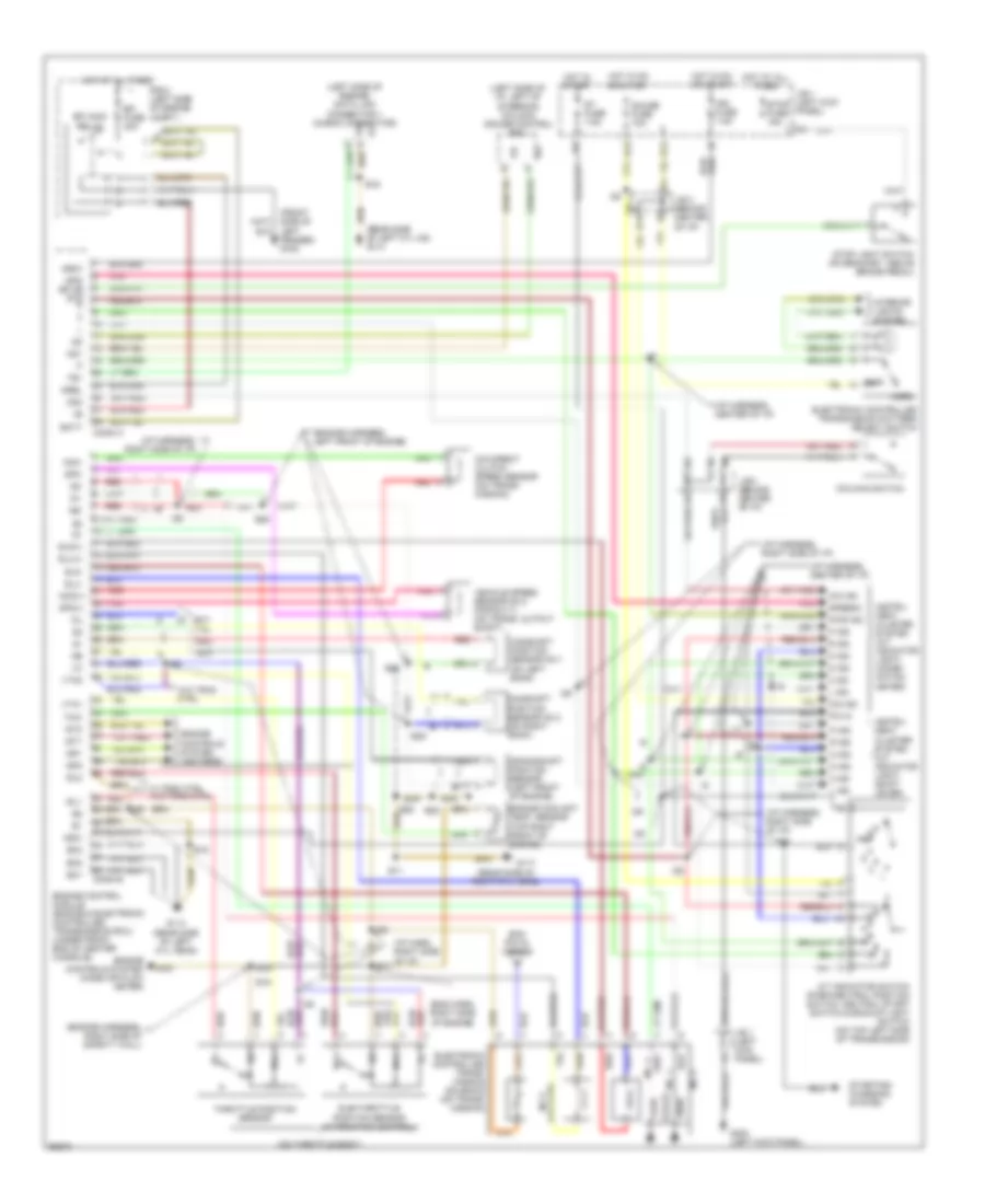
Transmission Wiring Diagram for Lexus SC 400 1996
List of elements for Transmission Wiring Diagram for Lexus SC 400 1996:
 English
Transmission Wiring Diagram for Lexus SC 400 1996
List of elements for Transmission Wiring Diagram for Lexus SC 400 1996: