AIR CONDITIONING
Heater Wiring Diagram for Ford Contour SE 2000

List of elements for Heater Wiring Diagram for Ford Contour SE 2000:
- (behind center dash panel) s274
- (bottom of right "a" pillar) g901
- Air temperature actuator (behind center of dash)
- C360
- C361
- Central junction box (under left side of dash)
- Def/flr
- Defrost
- Floor
- Fuse 23 15a
- Fuse 30a
- Heater blower motor (under right side of dash, behind glove box)
- Heater blower relay
- Heater blower series resistor (under right side of dash, near blower motor)
- Heater blower switch
- Heater mode switch
- High
- Hot at all times
- Hot in run or start
- Low
- Nca
- Off
- Pan/flr
- Panel
- S331 (near steering column)
- Side dash panel) s104
- Temperature door variable resistor (behind center of dash)
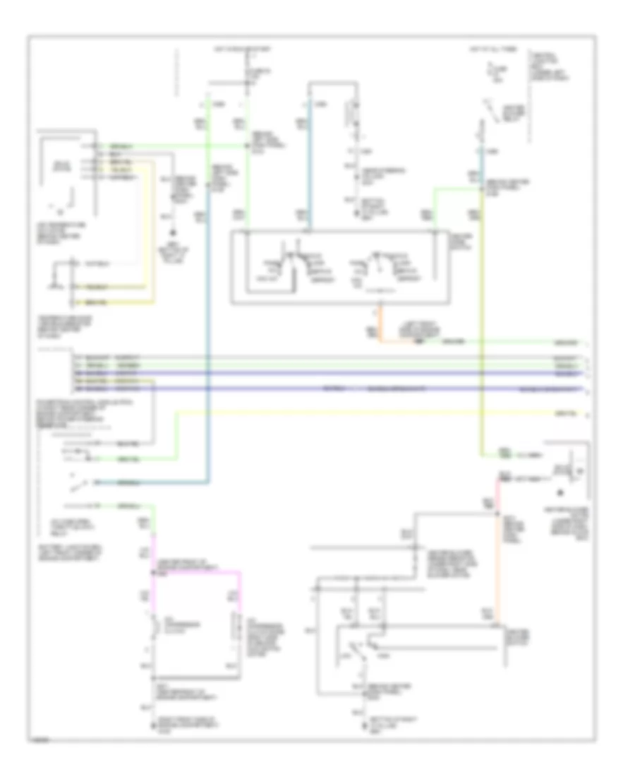
Manual A/C Wiring Diagram (1 of 2) for Ford Contour SE 2000
List of elements for Manual A/C Wiring Diagram (1 of 2) for Ford Contour SE 2000:
- (behind center dash panel) s166
- (behind left side dash panel) s104
- (behind left side dash panel) s136
- (bottom of right "a" pillar) g901
- (center front of engine compartment) s46
- (left front side of engine compartment) s167
- (near steering column) s331
- (right front side of engine compartment) g109
- 15s-re9a
- 91s-fa11
- 91s-pa13
- 91s-pa17
- 91s-pa7
- A/c
- A/c compressor clutch
- A/c compressor clutch diode (right side of second cooling fan motor)
- A/c wide open throttle (wot) relay
- Air temperature actuator (behind center of dash)
- Battery junction box (left front corner of engine compartment)
- C360
- C361
- C369
- Center dash panel) s244
- Central junction box (under left side of dash)
- Def/flr
- Defrost
- Floor
- Fuse 23 15a
- Fuse 30a
- G901 (bottom of right "a" pillar)
- Heater blower motor (under right side of dash, behind glove box)
- Heater blower relay
- Heater blower series resistor (under right side of dash, near blower motor)
- Heater blower switch
- Heater mode switch
- High
- Hot at all times
- Hot in run or start
- Low
- Max a/c
- Nca
- Off
- Pan/flr
- Panel
- Powertrain control module (pcm) (in right rear corner of engine compartment, behind power steering reservoir)
- S271 (center front of engine compartment)
- S274 (behind center dash panel)
- Solid state
- Temperature door variable resistor (behind center of dash)
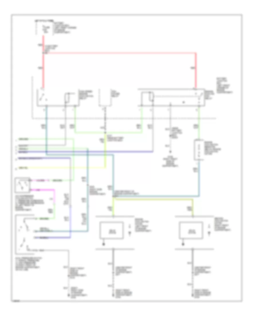
Manual A/C Wiring Diagram (2 of 2) for Ford Contour SE 2000
List of elements for Manual A/C Wiring Diagram (2 of 2) for Ford Contour SE 2000:
- (center front of engine compartment) s271
- (center front of engine compartment) s44
- (in battery junction box) s9
- (right front side of engine compartment) g109
- (right front side of engine compartment) s133
- A/c compressor cycling switch (1: pressure increasing) (2: pressure decreasing) (in left front of engine compartment)
- Battery junction box (left front corner of engine compartment)
- Battery junction box) s3003
- Dual pressure switch (1: normal pressure) (2: high pressure) (in right front of engine compartment, on a/c line)
- Engine cooling fan motor (left front of engine compartment)
- Engine cooling fan relay
- Engine cooling fan resistor (below engine cooling fan motor)
- Fuse 60a
- G109 (right front side of engine compartment)
- High speed engine cooling fan relay
- Hot at all times
- Nca
- Pcm power relay
- Red
- S147 (near battery junction box)
- S408 (right side engine compartment)
- Second cooling fan motor (right front of engine compartment)
- Solid state