AIR CONDITIONING
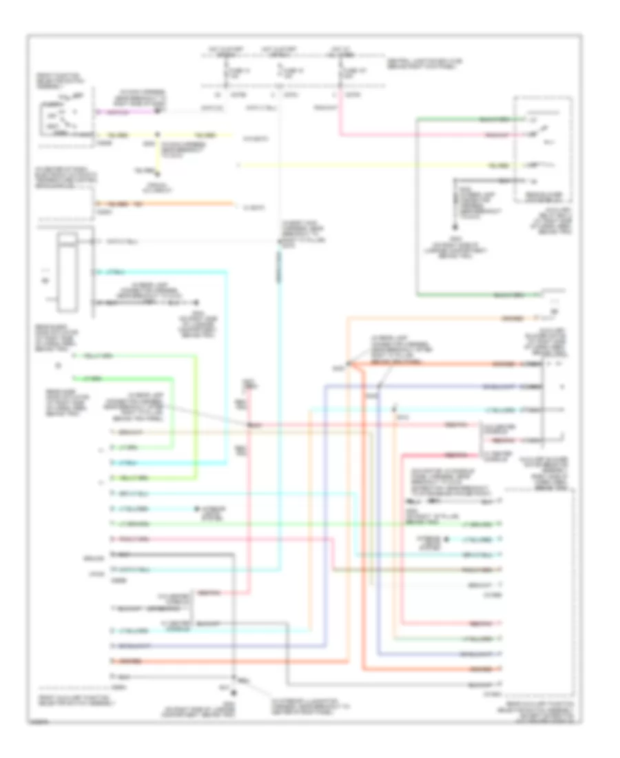
Automatic A/C Wiring Diagram (1 of 2) for Ford Expedition 2005

List of elements for Automatic A/C Wiring Diagram (1 of 2) for Ford Expedition 2005:
- (behind left kick panel) g301
- (behind right
- (behind right kick panel) g200
- (behind right side of dash) heater blower control module
- (in left side of dash) in-vehicle temperature/ humidity sensor
- (in main harness, near breakout to center of dash) s293
- (in main harness, near breakout to glove box lamp) s203
- (in main harness, near breakout to top of dash) s208
- (or 235)
- +/-
- Ambient air temperature sensor (behind right side of radiator grille)
- Auxiliary heater a/c circuit
- C228a
- C228b
- C270e
- C270g
- Central junction box (cjb) (behind right kick panel)
- Computer data lines system
- Defogger system
- Electronic automatic temperature control (eatc) module (in center of dash)
- Expedition
- Front blower motor relay
- Fuse 116 fuse 116 40a 40a
- Fuse 13 10a
- Fuse 5 7.5a
- G200 (behind right kick panel)
- Gnd
- Hot at all times
- Hot in start or run
- Hum sn
- Illum
- In temp
- In-vehicle temperature sensor (in left side of dash)
- Int temp
- Interior lights system
- Ms can+
- Ms can-
- Mtr ctrl
- Navigator
- Pos sig
- Pwr
- Remote solenoid assembly (under center of dash)
- Return
- Rr defr ind
- Rr defr req
- S203 (in main harness, near breakout to glove box lamp)
- S241 (main harness, near breakout to right side of dash)
- S277 (main harness, at breakout to brake pedal position switch)
- Side of dash) heater blower motor
- Sig rtn
- Sn pwr
- Vbatt
- Vbc fb
- Vbc hbr
- Vbc pwm
- Vpwr
- Vref
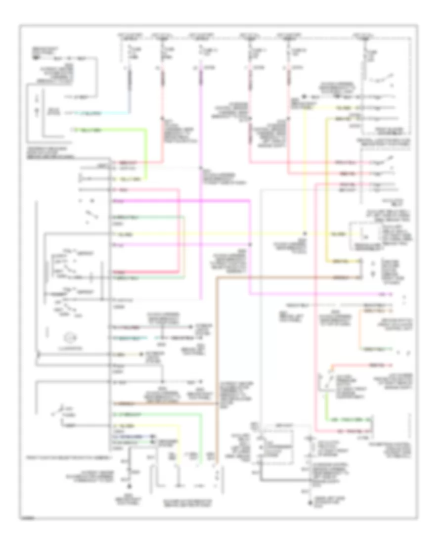
Automatic A/C Wiring Diagram (2 of 2) for Ford Expedition 2005
List of elements for Automatic A/C Wiring Diagram (2 of 2) for Ford Expedition 2005:
- (in engine control sensor harness, near breakout to g102) s113
- (in engine control sensor harness, near breakout to left side of engine compt) s104
- (in front heater blower motor harness, near breakout to right side of dash)
- A/c clutch field coil (at right front of engine)
- A/c clutch relay
- A/c compressor clutch diode
- A/c high pressure switch (at right front of engine compartment)
- Air bag sliding contact (under steering column)
- Auto lamps sens sig
- Auxiliary relay box 1 (at left front of engine compartment)
- C175b
- C2113b
- C218b
- C270a
- C270b
- Central junction box (cjb) (behind right kick panel)
- Cruise control system
- De-icing switch (on front of climate control unit)
- Driver temperature blend door actuator (behind center of dash)
- Fan speed (+)
- Fan speed (-)
- Fuse 11 10a
- Fuse 32 15a
- G100 (near left side of radiator)
- G301 (behind left kick panel)
- Hot at all times
- Hot in start or run
- Low charge protection switch (at right rear of engine compt)
- Microprocessor
- Nca
- Passenger temperature blend door actuator (behind center of dash)
- Pats ind
- Powertrain control module (on right side of firewall)
- Pressure sw
- Red
- Rtn sig
- S105 (in engine control sensor harness, near breakout to left side of engine compt)
- S2025 (in front heater blower motor harness, near breakout to right side of dash)
- S2026
- S208 (in main harness, near breakout to top of dash)
- Steering wheel radio switch
- Sunload sensor (to center of dash)
- Tan
- Temp (+)
- Temp (-)
- Vehicle security module (vsm) (under right side of dash)
Auxiliary Heater-A/C Wiring Diagram for Ford Expedition 2005
List of elements for Auxiliary Heater-A/C Wiring Diagram for Ford Expedition 2005:
- (in body main harness, near breakout to right "c" pillar) s319
- (in center of dash) electronic automatic temperature control (eatc) module
- (in interior illumination harness, near breakout to center of roof panel)
- (in main harness, near breakout to right side of dash) s241
- (in rear lamp connector harness, near breakout after right "c" pillar, behind trim panel)
- (in rear lamp connector harness, near breakout to c410) s424
- (navigator: in console panel harness, near breakout to c315) (expedition: near breakout to storage bin power point)
- (not used)
- (or red/pnk)
- +/-
- Auxiliary blower motor (at right side of cargo area, behind trim)
- Auxiliary blower motor resistor assembly (right side of cargo area, behind trim)
- Auxiliary relay box 2 (at right side of cargo area, behind trim)
- C228a
- C270e
- C270j
- C270n
- C294b
- C3198a
- C3198b
- C989a
- C989b
- Central junction box (cjb) (behind right kick panel)
- Def
- Floor
- Front auxiliary function selector switch assembly
- Front function selector switch assembly
- Fuse 107 30a
- Fuse 13 10a
- Fuse 18 10a
- G300 (on right ``b" pillar, behind trim)
- G404 (on right side of luggage compartment, behind trim)
- Ground
- Hot at all times
- Hot in start or run
- Interior lights system
- Manual a/c circuit
- Max
- Mix
- Nca
- Near breakout to c410)
- Norm
- Off
- Rear auxiliary function selector switch assembly (except expedition w/o center console)
- Rear blend door actuator (at right side of cargo area, behind trim)
- Rear blower motor relay
- Rear mode door actuator (at right side of cargo area, behind trim)
- Red/ pnk
- Red/pnk
- S205
- S230 (in main harness, near breakout to c210)
- S412
- S423
- S431
- S432
- S904
- Vent
- Vpwr
- W/ center console
- W/ eatc
- W/o center console
- W/o eatc
Manual A/C Wiring Diagram for Ford Expedition 2005
List of elements for Manual A/C Wiring Diagram for Ford Expedition 2005:
- (behind right kick panel) g200
- (in engine control sensor harness, near breakout to g102) s113
- (in front heater blower motor harness, in breakout to c237)
- (in front heater blower motor harness, in breakout to heater blower motor) s291
- (in main harness, near breakout to glove box lamp) s203
- (in main harness, near breakout to top of dash)
- (near left side of radiator) g100
- A/c clutch field coil (at right front of engine)
- A/c clutch relay
- A/c compressor clutch diode
- A/c high pressure switch (at right front of engine compartment)
- Auxiliary relay box 1 (at left side of cargo area, behind trim)
- Auxiliary relay box 1 (left side of cargo area, behind trim)
- Auxiliary relay box 2 (at right side of cargo area, behind trim) rear blower motor relay
- Blower motor resistor (behind center of dash)
- C175b
- C270a
- C270b
- C270e
- C270g
- C294a
- C294b
- C294c
- Central junction box (cjb) (behind right kick panel)
- De-icing switch (front of climate control unit)
- Defogger system
- Defrost
- Exterior lights system
- Floor
- Front blower motor relay
- Front function selector switch assembly
- Fuse 10a
- Fuse 11 10a
- Fuse 13 10a
- Fuse 32 15a
- Fuse 40a
- Fuse 7.5a
- G200 (behind right kick panel)
- G301 (behind left kick panel)
- Heater blower motor (behind right side of dash)
- Hot at all times
- Hot in start or run
- Illumination
- Interior lights system
- Low charge protection switch (at right rear of engine compt)
- Max
- Mix
- Near breakout to left side of engine compt) s104
- Norm
- Off
- Pnk
- Powertrain control module (pcm) (on right side of firewall)
- S105 (in engine control sensor harness, near breakout to left side of engine compt)
- S200
- S200 (in front heater blower motor harness, in breakout to c237)
- S202 (in main harness, near breakout to center of dash)
- S208
- S208 (in main harness, near breakout to top of dash)
- S230 (in main harness, near breakout to c210)
- S241 (in main harness, near breakout to right side of dash)
- S262 (in main harness, near breakout to front function selector switch assembly)
- S277 (in main harness, near breakout to brake pedal position switch)
- Solid state
- Temperature blend door actuator (behind center of dash)
- Vbatt
- Vent