AIR CONDITIONING
A/C Wiring Diagram, Auto A/C for Ford Explorer 1997

List of elements for A/C Wiring Diagram, Auto A/C for Ford Explorer 1997:
- (eng harn, between a/c clutch diode & a/c comp clutch solenoid breakout)
- (eng harn, left front of engine compartment)
- (eng harn, left side of eng compt)
- (eng harn, near a/c comp clutch solenoid)
- (engine harn, left side of eng compt)
- (engine harn, rear of engine compartment) s144
- (i/p harn, behind center of i/p)
- (i/p harn, near instrument panel breakout)
- (i/p harn, near right door jamb) s240
- (i/p harn, right side of i/p)
- (right side of engine compt)
- A/c compressor clutch solenoid
- A/c clutch cycling pressure switch (right side of engine compartment)
- A/c clutch diode
- A/c clutch out
- A/c plenum)
- A/c pressure cutoff switch (left side of engine compartment)
- Ambient temp input
- Ambient temperature sensor (left front of engine compartment)
- Battery
- Blend door act
- Blend door actuator (behind right side of i/p, top of
- Blend door pot
- Blend door ref
- Blower motor
- Blower motor relay (in auxiliary relay box 2)
- Blower motor speed
- Blower motor speed controller (near blower motor)
- Blower speed fback
- C297
- C298
- Data line
- Data link connector (dlc) (behind left side of i/p)
- Electronic automatic temperature control (eatc) module (center of i/p)
- Eng/met conv
- Fuse 10a
- Fuse 15a
- Fuse 50a
- Fuse 7.5a
- G103
- G103 (right side of eng compartment)
- G104 (left rear corner of engine compartment)
- G104 (left rear corner of engine compt)
- G201 (under right side of i/p)
- Ground
- Hot at all times
- Hot in run
- Ignition
- Illumination
- In car temp sens
- In-car temperature sensor
- Interior fuse panel
- Interior lights system
- Med
- Message center
- Off
- Pcm power relay
- Power distribution box
- Powertrain control module (pcm) (on right side of safety wall)
- Rear blower motor
- Rear air door actuator (in i/p console)
- Rear blower motor relay (behind right side of i/p)
- Rear blower motor resistor (in i/p console)
- Rear integrated control panel (ricp)
- Red
- Relay signal
- S100
- S133
- S154
- S158
- S161
- S205
- S206
- S209
- S211
- S229
- S231 (body harn, in i/p console)
- S241
- S263
- Sensor ground
- Sun load sensor (top right side of i/p, above glove box)
- Sunload sens input
- Wot a/c relay (in power distribution box)
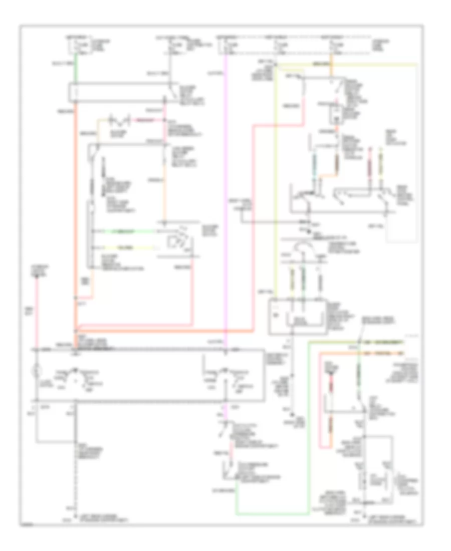
A/C Wiring Diagram, Manual A/C for Ford Explorer 1997
List of elements for A/C Wiring Diagram, Manual A/C for Ford Explorer 1997:
- (body harn, in i/p console)
- (eng harn, between a/c clutch diode & a/c comp clutch solenoid breakout)
- (eng harn, rear of engine compt)
- (in auxiliary relay box 2)
- (left rear corner of engine compartment)
- A/c clutch cycling pressure switch (right side of engine compartment)
- A/c clutch diode
- A/c compres- sor clutch solenoid
- A/c pressure cutoff switch (left side of engine compartment)
- Blend door actuator (behind right side of i/p, on a/c plenum)
- Blower motor
- Blower motor relay (in auxiliary relay box 2)
- Blower motor resistor (near blower motor)
- Blower motor switch
- C231
- C276
- Cold
- Def
- Def/flr
- Flr
- Fuse 15a
- Fuse 50a
- Fuse 7.5a
- G103 (right side of engine compartment)
- G104
- G201 (right side of i/p)
- Heater-a/c control assembly
- High speed blower relay
- Hot at all times
- Hot in run
- Illumi- nation
- Interior fuse panel
- Interior lights system
- Low
- Max
- Med
- Norm
- Off
- Pan/flr
- Panel
- Pcm power relay
- Power distribution box
- Powertrain control module (pcm) (on right side of safety wall)
- Rear air door actuator
- Rear blower motor
- Rear blower motor relay (behind right side of i/p)
- Rear blower motor resistor (in i/p console)
- Rear inte- grated control panel
- Red
- S100
- S133 (eng harn, near a/c comp clutch solenoid)
- S144
- S158 (engine harn, left side of eng compt)
- S170 (i/p harness, near blower motor breakout)
- S171
- S200 (i/p harness, near radio breakout)
- S229 (i/p harn, behind center of i/p)
- S231
- S240 (i/p harn, near right door jamb)
- S257 (i/p harn, near blower motor switch breakout)
- Solid state
- Temperature control potentiometer
- Warm
- Wot a/c relay (in power distribution box)