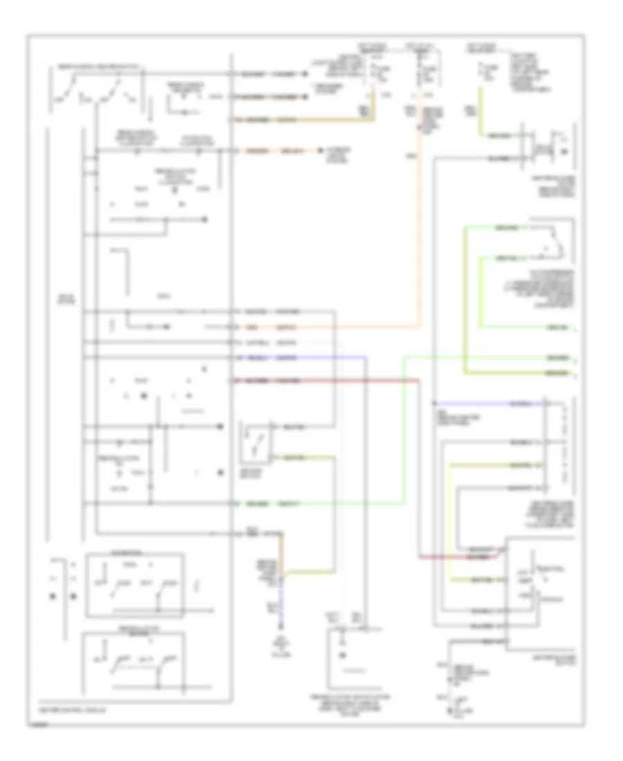
AIR CONDITIONING
Heater Wiring Diagram for Ford Focus SE 2002

List of elements for Heater Wiring Diagram for Ford Focus SE 2002:
- (behind center dash panel) s12
- (behind center dash panel) s24
- (left "a" pillar) g14
- (right "a" pillar) g41
- 15-fa13
- 29-fa13
- 29s-le10
- 31s-fa26
- 31s-hb21
- 31s-hb31
- 32-fa76
- 33-fa76
- 91-fa13
- 91s-fa20
- Battery junction box (bjb) (in left rear corner of engine compartment)
- C10
- C16
- Central junction box (cjb) (behind left side of dash)
- De-icing switch
- Defogger system
- Fuse 30a
- Fuse 7.5a
- Heater blower motor (behind right side of dash)
- Heater blower series resistor (under right side of dash, next to blower motor)
- Heater blower switch
- Heater control module
- High
- Hot at all times
- Hot in run or start
- Interior lights system
- Low
- Maximum speed
- Med
- Neutral
- Off
- Rear window heater on
- Rear window heater switch
- Rear window heater switch illumination
- Recirc on
- Recirculation air actuator (behind right side of dash, next to blower motor)
- Recirculation on
- Recirculation switch
- Recirculation switch illumination
- Solid state
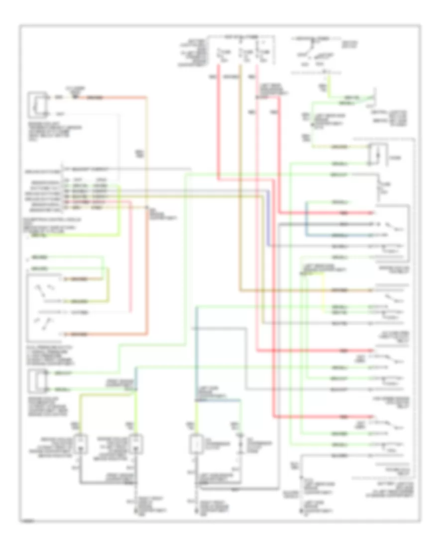
Manual A/C Wiring Diagram, Except SVT (1 of 2) for Ford Focus SE 2002
List of elements for Manual A/C Wiring Diagram, Except SVT (1 of 2) for Ford Focus SE 2002:
- (behind center dash panel) s12
- (behind center dash panel) s49
- (behind center dash panel) s6
- (left "a" pillar) g14
- 15-fa13
- 15s-fa17
- 29-fa13
- 29s-le10
- 31s-fa26
- 31s-hb22
- 31s-hb31
- 32-fa76
- 33-fa76
- 91-fa13
- 91s-fa20
- A/c compressor cycling switch (1: pressure increasing) (2: pressure decreasing) (in left rear corner of engine compartment)
- A/c on
- A/c switch
- A/c switch illumination
- Battery junction box (bjb) (in left rear corner of engine compartment)
- C10
- C16
- Central junction box (cjb) (behind left side of dash)
- De-icing switch
- Defogger system
- Fuse 40a
- Fuse 7.5a
- G41 (right "a" pillar)
- Heater blower motor (behind right side of dash)
- Heater blower series resistor (under right side of dash, next to blower motor)
- Heater blower switch
- Heater control module
- High
- Hot at all times
- Hot in run or start
- Interior lights system
- Low
- Maximum
- Med
- Neutral
- Off
- Rear window heater on
- Rear window heater switch
- Rear window heater switch illumination
- Recirculation air actuator (behind right side of dash, next to blower motor)
- Recirculation on
- Recirculation switch
- Recirculation switch illumination
- S24 (behind center dash panel)
- Solid state
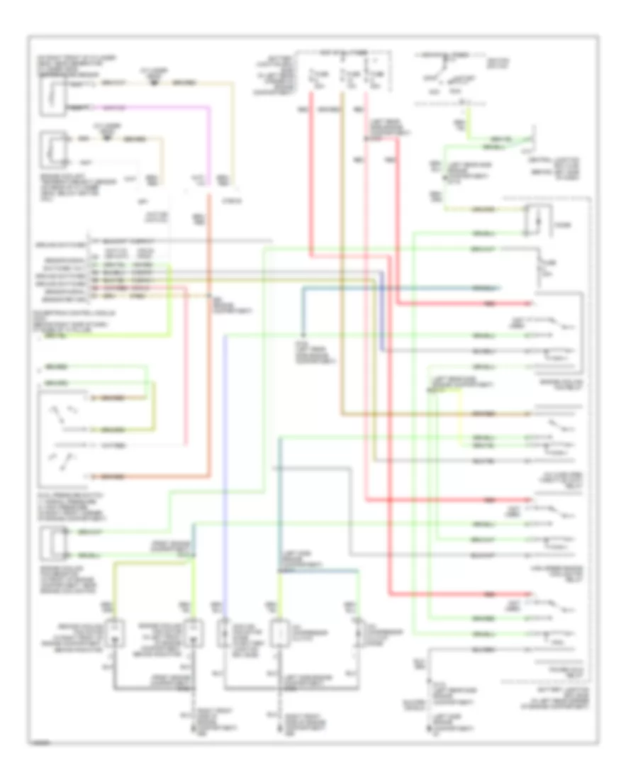
Manual A/C Wiring Diagram, Except SVT (2 of 2) for Ford Focus SE 2002
List of elements for Manual A/C Wiring Diagram, Except SVT (2 of 2) for Ford Focus SE 2002:
- (cylinder head) s98
- (front engine compartment) s137
- (front engine compartment) s138
- (left rear side engine compartment) s107
- (left rear side engine compartment) s117
- (left rear side engine compartment) s119
- (left side engine compartment) g1
- (left side engine compartment) s109
- (left side engine compartment) s111
- (not used)
- (on right front of cylinder head, near generator) cylinder head temperature sensor
- (right front side of engine compartment) g56
- 15s-re8
- 31s-fa11
- 31s-pa17
- 31s-pa7
- 8-pa13
- 8-rj33 8-rj5
- 9-re8
- A/c compressor clutch
- A/c compressor clutch diode
- A/c wide open throttle (wot) relay
- Acc
- Battery junction box (bjb) (in left rear corner of engine compartment)
- C13
- Central junction box (cjb) (behind left side of dash)
- Cooling fan motor diode (in battery junction box (bjb))
- Diode
- Dual pressure switch (1: normal pressure) (2: high pressure) (in right front corner of engine compartment)
- Engine coolant temperature (ect) sensor (on rear of cylinder head, below ignition coil)
- Engine cooling fan motor (in left front of engine compartment, behind radiator)
- Engine cooling fan relay
- Engine cooling fan resistor (in front of engine compartment, near engine cooling fan)
- Fuse 10a
- Fuse 20a
- Fuse 30a
- Fuse 50a
- Ground switched
- High speed engine cooling fan relay
- Hot at all times
- Ignition switch
- Nca
- Off
- Power hold relay
- Powertrain control module (pcm) (behind right side of dash, at base of "a" pillar)
- Red
- Run
- S108 (left rear side engine compartment)
- S118 (left rear side engine compartment)
- S63 (engine compartment)
- Second cooling fan motor (in right front of engine compartment, behind radiator)
- Sensor return
- Sensor signal
- Sp1
- Start
- Switched volt
- Ztec-e
Manual A/C Wiring Diagram, SVT (1 of 2) for Ford Focus SE 2002
List of elements for Manual A/C Wiring Diagram, SVT (1 of 2) for Ford Focus SE 2002:
- (behind center dash panel) s12
- (behind center dash panel) s49
- (behind center dash panel) s6
- (left "a" pillar) g14
- 15-fa13
- 15s-fa17
- 29-fa13
- 29s-le10
- 31s-fa26
- 31s-hb22
- 31s-hb31
- 32-fa76
- 33-fa76
- 91-fa13
- 91s-fa20
- A/c compressor cycling switch (1: pressure increasing) (2: pressure decreasing) (in left rear corner of engine compartment)
- A/c on
- A/c switch
- A/c switch illumination
- Battery junction box (bjb) (in left rear corner of engine compartment)
- C10
- C16
- Central junction box (cjb) (behind left side of dash)
- De-icing switch
- Defogger system
- Fuse 40a
- Fuse 7.5a
- G41 (right "a" pillar)
- Heater blower motor (behind right side of dash)
- Heater blower series resistor (under right side of dash, next to blower motor)
- Heater blower switch
- Heater control module
- High
- Hot at all times
- Hot in run or start
- Interior lights system
- Low
- Maximum
- Med
- Neutral
- Off
- Rear window heater on
- Rear window heater switch
- Rear window heater switch illumination
- Recirculation air actuator (behind right side of dash, next to blower motor)
- Recirculation on
- Recirculation switch
- Recirculation switch illumination
- S24 (behind center dash panel)
- Solid state
Manual A/C Wiring Diagram, SVT (2 of 2) for Ford Focus SE 2002
List of elements for Manual A/C Wiring Diagram, SVT (2 of 2) for Ford Focus SE 2002:
- (cylinder head) s98
- (front engine compartment) s137
- (front engine compartment) s138
- (left rear side engine compartment) s107
- (left rear side engine compartment) s117
- (left rear side engine compartment) s119
- (left side engine compartment) g1
- (left side engine compartment) s109
- (left side engine compartment) s111
- (not used)
- (right front side of engine compartment) g56
- 15s-re8
- 31s-fa11
- 31s-pa17
- 31s-pa7
- 8-pa13
- 8-rj5
- 9-re8
- A/c compressor clutch
- A/c compressor clutch diode
- A/c wide open throttle (wot) relay
- Acc
- Battery junction box (bjb) (in left rear corner of engine compartment)
- C13
- Central junction box (cjb) (behind left side of dash)
- Diode
- Dual pressure switch (1: normal pressure) (2: high pressure) (in right front corner of engine compartment)
- Engine coolant temperature (ect) sensor (on rear of cylinder head, below ignition coil)
- Engine cooling fan motor (in left front of engine compartment, behind radiator)
- Engine cooling fan relay
- Engine cooling fan resistor (in front of engine compartment, near engine cooling fan)
- Fuse 10a
- Fuse 20a
- Fuse 30a
- Fuse 50a
- Ground switched
- High speed engine cooling fan relay
- Hot at all times
- Ignition switch
- Off
- Power hold relay
- Powertrain control module (pcm) (behind right side of dash, at base of "a" pillar)
- Red
- Run
- S118 (left rear side engine compartment)
- S63 (engine compartment)
- Second cooling fan motor (in right front of engine compartment, behind radiator)
- Sensor return
- Sensor signal
- Start
- Switched volt