AIR CONDITIONING
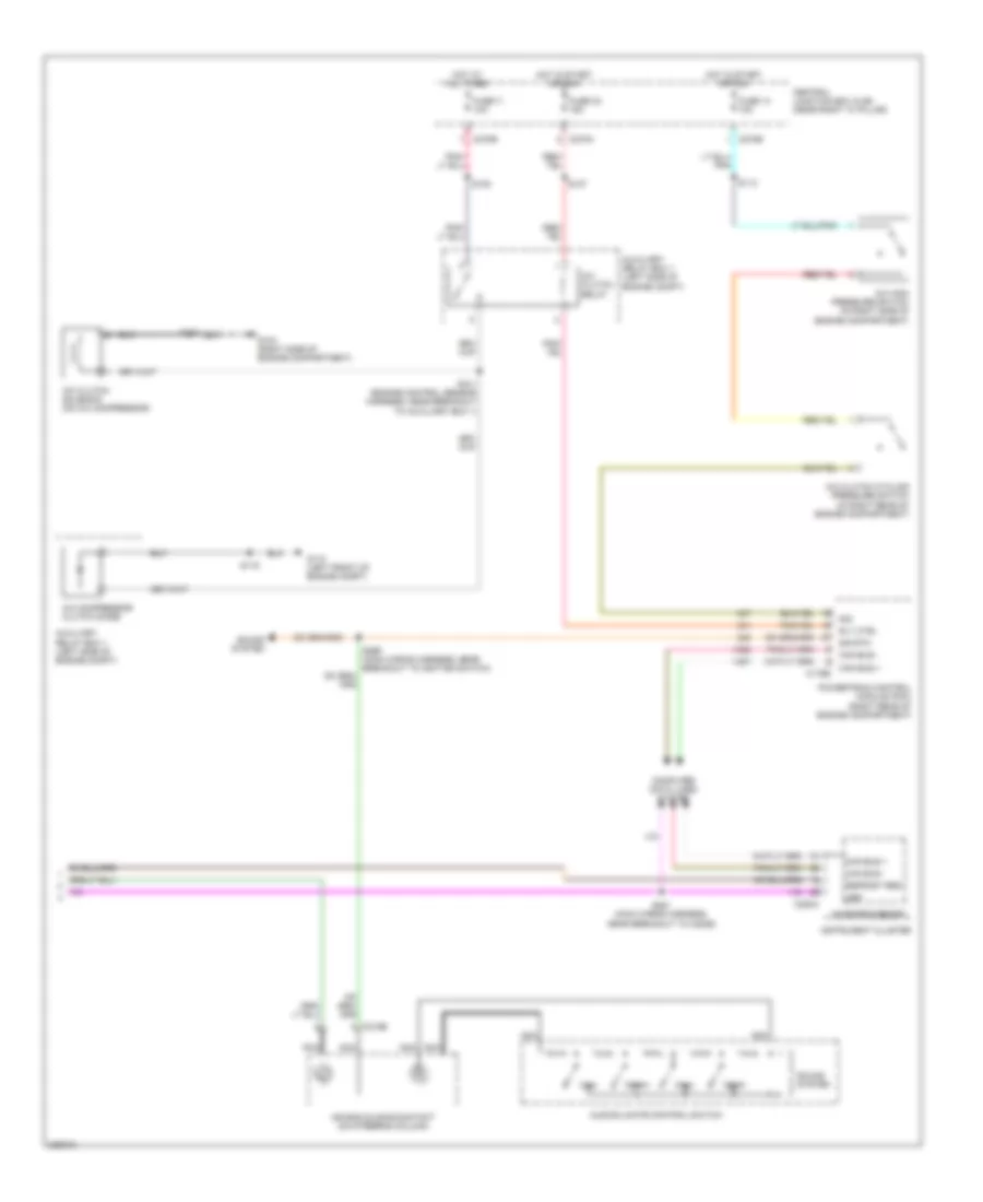
Automatic A/C Wiring Diagram (1 of 2) for Ford Pickup F250 Super Duty 2006

List of elements for Automatic A/C Wiring Diagram (1 of 2) for Ford Pickup F250 Super Duty 2006:
- (heater blower motor wiring harness, in breakout to c299)
- (in right front footwell) g203
- +/-
- Anti- theft system
- Autolamp/sunload sensor (on top left side of dash)
- Body security module (regular cab: left "b" pillar) (super cab/crew cab: on left back wall of cab)
- C228a
- C228b
- C270e
- C270g
- C3008b
- Central junction box (cjb) (near right "a" pillar)
- Defogger system
- Defrost req
- Electronic automatic temperature control (eatc) module (center of dash)
- Fresh/recirculation door actuator (behind right side of dash)
- Front blower motor (behind dash)
- Front blower motor relay
- Front blower motor speed controller (right "a" pillar)
- Fuse 116 30a
- Fuse 13 10a
- Fuse 5 7.5a
- G200 (left "a" pillar)
- Gnd
- High ind sig
- High/low on/off sig vref
- Hot at all times
- Hot in start or run
- In-vehicle temperature sensor (behind dash panel)
- Interior lights system
- Light sensor
- Low ind sig
- Low ind sig high/low on/off sig
- Microprocessor
- Mtr ctrl
- Panel mode actuator (behind center of dash)
- Pats ind
- Red
- Rly ctrl
- Rly sw pwr
- S202
- S204 (heater blower motor wiring harness, in breakout to c299)
- S208
- S210
- S236
- S286 (main wiring harness, near breakout to front blower motor speed controller)
- Seats system
- Sens
- Sig
- Sig rtn
- Sun sensor
- Temperature blend door actuator (behind center of dash)
- Ubp
- Vbatt
- Vpwr
- Vref
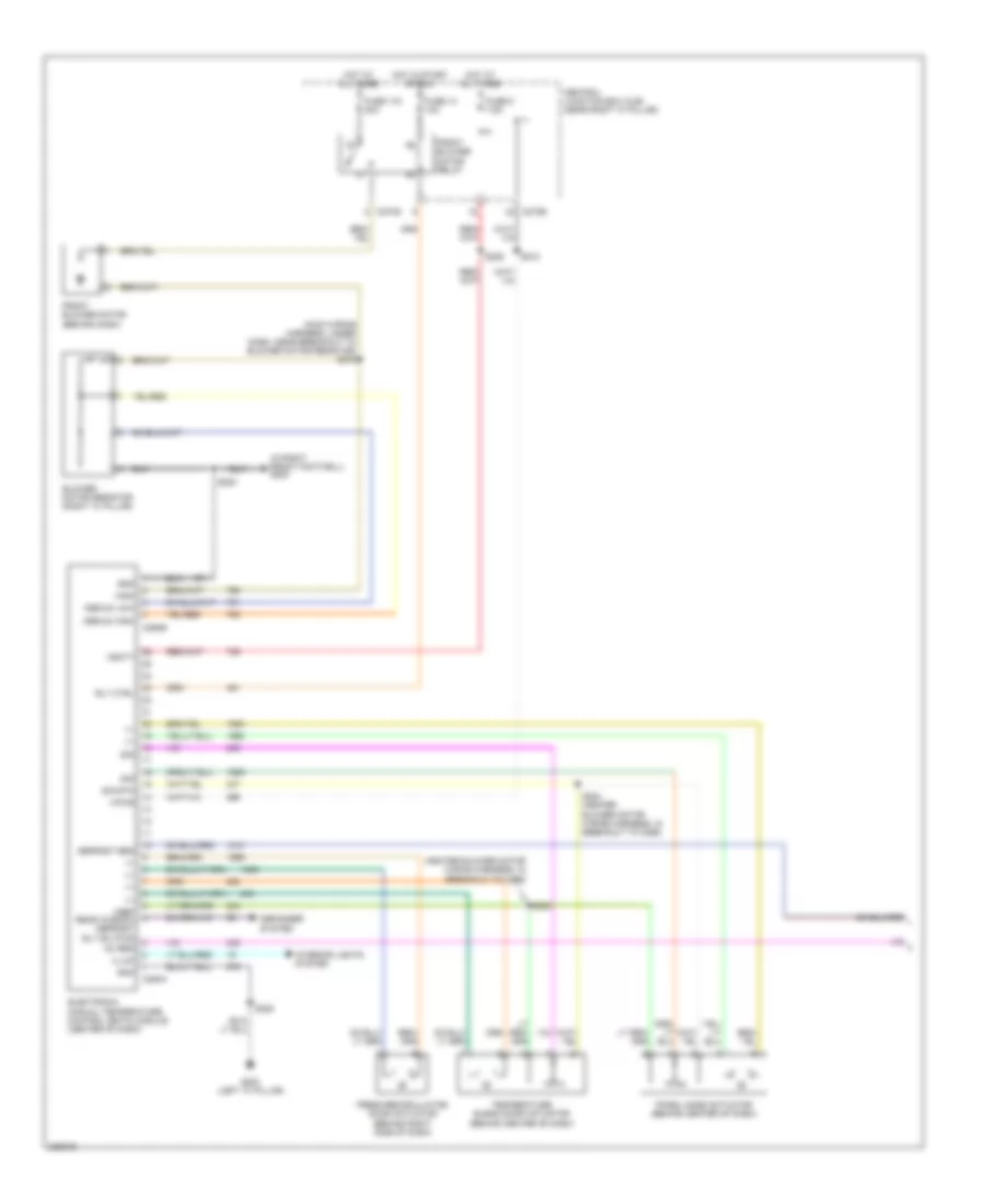
Automatic A/C Wiring Diagram (2 of 2) for Ford Pickup F250 Super Duty 2006
List of elements for Automatic A/C Wiring Diagram (2 of 2) for Ford Pickup F250 Super Duty 2006:
- A/c clutch cycling pressure switch (in right rear of engine compartment)
- A/c clutch relay
- A/c clutch solenoid (on a/c compressor)
- A/c compressor clutch diode
- A/c high pressure switch (in right side of engine compartment)
- Air bag sliding contact (on steering column)
- Audio/climate control switch
- Auxiliary relay box 1 (left side of engine compt)
- C175b
- C218b
- C220a
- C270a
- C270b
- Can bus +
- Can bus -
- Central junction box (cjb) (near right "a" pillar)
- Computer data lines system
- Defrost req
- Fan+
- Fan-
- Fuse 11 10a
- Fuse 14 10a
- Fuse 32 15a
- G104 (right side of engine compartment)
- G110 (left front of engine compt)
- Hot at all times
- Hot in start or run
- Instrument cluster
- Microprocessor
- Nca
- Powertrain control module (pcm) (right rear of engine compartment)
- Rly ctrl
- S100
- S101 (engine control sensor harness, near breakout to auxiliary box 1)
- S105
- S107
- S112
- S116
- S281 (main wiring harness, near breakout to c2026)
- Sig
- Sig rtn
- Sound system
- Temp+
- Temp-
- Ubp
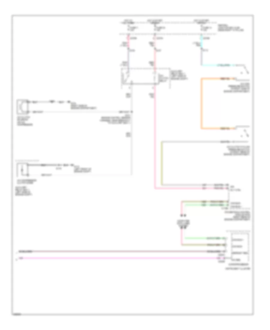
Manual A/C Wiring Diagram (1 of 2) for Ford Pickup F250 Super Duty 2006
List of elements for Manual A/C Wiring Diagram (1 of 2) for Ford Pickup F250 Super Duty 2006:
- (heater blower motor wiring harness, in breakout to c299)
- (in right front footwell) g203
- (main wiring harness, under dash, near breakout to blower motor resistor) s275
- +/-
- Ac req
- Blower motor resistor (right "a" pillar)
- C270e
- C270g
- C294a
- C294b
- Central junction box (cjb) (near right "a" pillar)
- Defogger system
- Defrost req
- Electronic manual temperature control (emtc) module (center of dash)
- Fresh/recirculation door actuator (behind right side of dash)
- Front blower motor (behind dash)
- Front blower motor relay
- Fuse 116 30a
- Fuse 13 10a
- Fuse 5 7.5a
- G200 (left "a" pillar)
- Gnd
- High
- Hot at all times
- Hot in start or run
- Illum
- Interior lights system
- Medium high
- Medium low
- Panel mode actuator (behind center of dash)
- Rly ctrl
- S200
- S202
- S204 (heater blower motor wiring harness, in breakout to c299)
- S208
- S210
- S236
- Sig
- Sig rtn
- Temperature blend door actuator (behind center of dash)
- Vbatt
- Vpwr
- Vref rear window defrost rly sw pwr
Manual A/C Wiring Diagram (2 of 2) for Ford Pickup F250 Super Duty 2006
List of elements for Manual A/C Wiring Diagram (2 of 2) for Ford Pickup F250 Super Duty 2006:
- A/c clutch cycling pressure switch (in right rear of engine compartment)
- A/c clutch relay
- A/c clutch solenoid (on a/c compressor)
- A/c compressor clutch diode
- A/c high pressure switch (in right side of engine compartment)
- Ac req
- Auxiliary relay box 1 (left side of engine compt)
- C175b
- C220a
- C220b
- C270a
- C270b
- Can bus +
- Can bus -
- Central junction box (cjb) (near right "a" pillar)
- Computer data lines system
- Defrost req
- Fuse 11 10a
- Fuse 14 10a
- Fuse 32 15a
- G104 (right side of engine compartment)
- G110 (left front of engine compt)
- Hot at all times
- Hot in start or run
- Instrument cluster
- Microprocessor
- Powertrain control module (pcm) (right rear of engine compartment)
- Rly ctrl
- S100
- S101 (engine control sensor harness, near breakout to auxiliary box 1)
- S105
- S107
- S112
- S116
- Sig