AIR CONDITIONING
2.0L
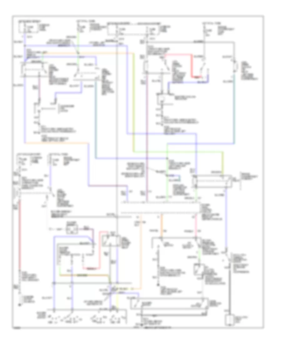
2.0L, A/C Wiring Diagram for Ford Probe GTS 1997

List of elements for 2.0L, A/C Wiring Diagram for Ford Probe GTS 1997:
- (behind left side of i/p)
- (behind right side of i/p)
- (below center front of center console)
- (i/p harn, behind center of i/p)
- (left front of vehicle, near left fog lamp)
- (left rear of engine compartment)
- (right front of engine, on compressor)
- A/c clutch cycling pressure switch (right rear of engine compt on accumulator)
- A/c clutch field coil
- A/c clutch switch
- A/c clutch thermal protection switch
- A/c high pressure cutout/fan switch (right front of engine compartment)
- A/c relay
- A/c switch
- Blower assembly
- Blower motor
- Blower motor resistor
- Blower motor switch
- Blower switch
- C214
- C215
- Electric cooling fan motor
- Engine compartment fuse box
- Fan switch
- Fuse 15a
- Fuse 40a
- G100
- G100 (left front of vehicle, near left fog lamp)
- G202
- High speed blower motor relay
- High speed cooling fan relay
- Hot at all times
- Hot in accy or run
- Hot in run or start
- Interior fuse panel
- Lo med
- Low speed blower motor relay (left rear of engine compartment)
- Low speed cooling fan relay (left front of vehicle on upper radiator support)
- Med
- Mode selector switch
- Nca
- Power- train control module
- Red
- S109 (front harness, near safety wall grommet)
- S142 (front harness, left rear of engine compt)
- S151 (front harn, left rear of eng compt)
- S158 (front harn, near safety wall grommet)
- S199 (front harn, near electric cooling fan motor breakout)
- S2000
- S2001
- S213 (i/p harn, behind left side i/p i/p)
- S231 (front harn, near interior fuse panel connector breakout)
- S241 (i/p harn, left side of i/p)
- Starter motor/ solenoid
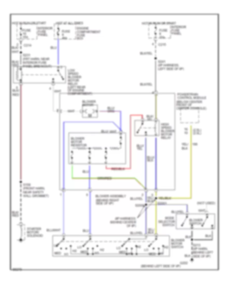
Heater Wiring Diagram for Ford Probe GTS 1997
List of elements for Heater Wiring Diagram for Ford Probe GTS 1997:
- (2.5l) (2.0l)
- (behind left side of i/p)
- (behind right side of i/p)
- (i/p harness, behind center of i/p)
- (not used)
- Blower assembly
- Blower motor
- Blower motor resistor
- Blower motor switch
- Blower switch
- C214
- C215
- Engine compartment fuse box
- Fuse 15a
- Fuse 40a
- G202
- High speed blower motor relay
- Hot at all times
- Hot in run or start
- Interior fuse panel
- Low speed blower motor relay (left rear of engine compartment)
- Med
- Mode
- Powertrain control module (below center front of center console)
- Red
- S158 (front harn, near safety wall grommet)
- S2000
- S2001
- S213 (i/p harn, behind left side of i/p)
- S231 (frt harn, near interior fuse panel breakout)
- S241 (i/p harness, left side of i/p)
- Selector
- Starter motor/ solenoid
- Switch
2.5L
2.5L, A/C Wiring Diagram for Ford Probe GTS 1997
List of elements for 2.5L, A/C Wiring Diagram for Ford Probe GTS 1997:
- (behind left side of i/p)
- (behind right side of i/p)
- (emission harn, right rear of eng compt) (a/t) or (emission harn, left side of engi) (m/t)
- (front harn, near eng compt fuse box breakout)
- (i/p harn, behind center of i/p)
- (left rear of engine compartment)
- (right front of engine, on compressor)
- A/c clutch cycling pressure switch (right rear of engine compt on accumulator)
- A/c clutch field coil
- A/c clutch switch
- A/c clutch thermal protection switch
- A/c high pressure cutout/fan switch (right front of engine compartment)
- A/c relay
- A/c switch
- Blower assembly
- Blower motor
- Blower motor resistor
- Blower motor switch
- Blower switch
- C214
- C215
- Condenser fan motor
- Data link connector (left side of engine compartment)
- Engine compartment fuse box
- Fan switch
- Fuse 15a
- Fuse 40a
- G100 (left front of vehicle, near left fog lamp)
- G202
- High speed blower motor relay
- High speed conden- ser fan relay (on right side of engine compart- ment fuse box)
- High speed cooling fan relay
- Hot at all times
- Hot in accy or run
- Hot in run or start
- Interior fuse panel
- Low speed blower motor relay (left rear of engine compartment)
- Low speed conden- ser fan relay (on right side of engine compart- ment fuse box)
- Low speed cooling fan relay (left front of vehicle on upper radiator support)
- Med
- Mode selector switch
- Nca
- Nca electric cooling fan motor
- Power- train control module (below center front of center console)
- Red
- S111 (front harn, near electric cooling fan motor breakout)
- S141
- S143 (front harn, near eng compt fuse box breakout)
- S151 (front harn, left rear of eng compt)
- S158 (front harn, near safety wall grommet)
- S188 (front harn, near left headlamp breakout)
- S192
- S199 (front harn, near electric cooling fan motor breakout)
- S2000
- S2001
- S213 (i/p harn, behind left side i/p i/p)
- S231 (front harn, near interior fuse panel connector breakout)
- S241
- Starter motor/ solenoid
Heater Wiring Diagram for Ford Probe GTS 1997
List of elements for Heater Wiring Diagram for Ford Probe GTS 1997:
- (2.5l) (2.0l)
- (behind left side of i/p)
- (behind right side of i/p)
- (i/p harness, behind center of i/p)
- (not used)
- Blower assembly
- Blower motor
- Blower motor resistor
- Blower motor switch
- Blower switch
- C214
- C215
- Engine compartment fuse box
- Fuse 15a
- Fuse 40a
- G202
- High speed blower motor relay
- Hot at all times
- Hot in run or start
- Interior fuse panel
- Low speed blower motor relay (left rear of engine compartment)
- Med
- Mode
- Powertrain control module (below center front of center console)
- Red
- S158 (front harn, near safety wall grommet)
- S2000
- S2001
- S213 (i/p harn, behind left side of i/p)
- S231 (frt harn, near interior fuse panel breakout)
- S241 (i/p harness, left side of i/p)
- Selector
- Starter motor/ solenoid
- Switch