AIR CONDITIONING
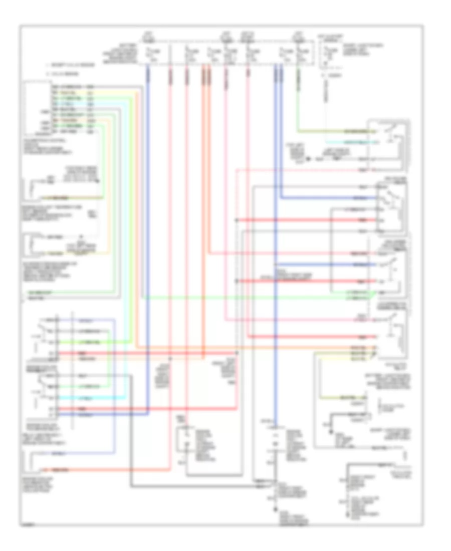
Automatic A/C Wiring Diagram (1 of 2) for Ford Taurus SEL 2005

List of elements for Automatic A/C Wiring Diagram (1 of 2) for Ford Taurus SEL 2005:
- (behind center of dash) g200
- (behind center of dash) g201
- (right front side of engine) s113
- (right rear side of engine compartment) g102
- (upper left side of dash) s237
- +/-
- Acp+
- Acp-
- Ambient air temperature sensor (behind right side of front bumper)
- Autolamp
- Autolamp/ sunload sensor (in dash, above glove box)
- Blower motor relay
- C2280b
- C2280e
- Computer data
- Dual pressure switch (behind a/c compressor)
- Front blower motor speed controller (behind center of dash, near hvac unit)
- Fuse 31 10a
- Fuse 33 15a
- Fuse 8 40a
- Gnd
- High pressure
- Hot at all times
- Hot in run
- In-vehicle temperature sensor
- Instrument cluster
- Integrated control panel (icp)
- Lines system
- Low charge protection switch
- Low current board
- Microprocessor
- Ms can+
- Ms can-
- Normal pressure
- Remote climate control (rcc) module (behind center of dash, near glove box)
- S205 (top center of dash)
- S237 (upper left side of dash)
- S246 (behind center of dash)
- Sig
- Sig rtn
- Smart junction box (under left side of dash)
- Sound systems
- Sunload
- Sw gnd
- Tan
- Temperature blend door actuator (under right side of dash)
- Vbatt
- Vpwr
- Vref
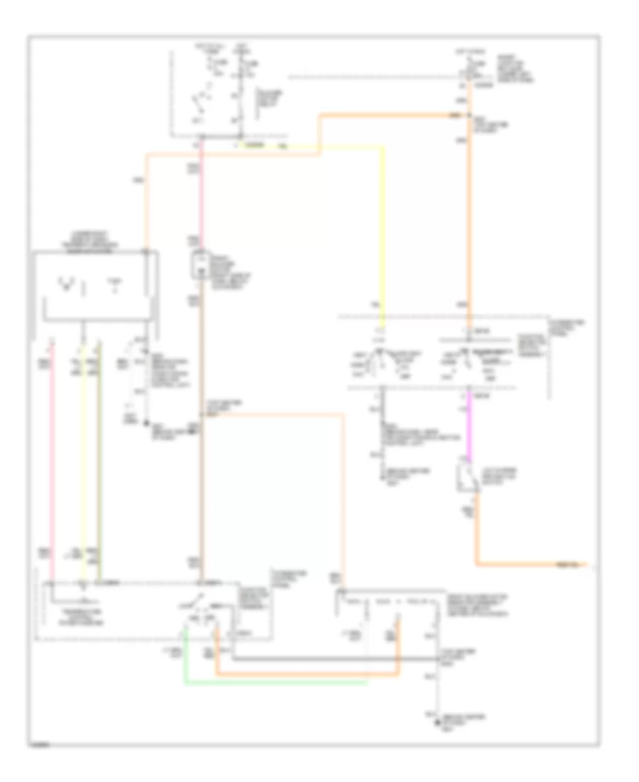
Automatic A/C Wiring Diagram (2 of 2) for Ford Taurus SEL 2005
List of elements for Automatic A/C Wiring Diagram (2 of 2) for Ford Taurus SEL 2005:
- (3.0l 24-vlv) (3.0l 12-vlv)
- (3.0l, 24-valve: right rear side of engine compartment) g102
- (left side of engine compt) s137
- (right front side of engine) s113
- (top left side of engine compt) g107
- (top right rear side of engine) s104 s116
- 3.0l 2v engine
- 87a
- A/c clutch diode
- A/c clutch field coil
- A/c clutch relay
- Battery junction box (front center of engine compartment, behind radiator)
- Battery junction box (front center of engine compt, behind radiator)
- C2280a
- C2280c
- Engine coolant temperature (ect) sensor (on rear of engine block, near thermostat)
- Engine cooling fan 1 (in front of engine compt, behind radiator)
- Engine cooling fan 2 (in front of engine compt, behind radiator)
- Engine cooling fan brake relay
- Engine cooling fan relay
- Engine cooling fan resistor (near electric cooling fans)
- Evaporator discharge air temperature sensor (early production) (behind center of dash, near glove box)
- Except 3.0l 2v engine
- Fuse 10a
- Fuse 15a
- Fuse 20a
- Fuse 2a
- Fuse 30a
- Fuse 40a
- G105 (right front side of engine compartment)
- G202 (at base of left "a" pillar)
- High speed fan control relay
- Hot at all times
- Hot in start or run
- Low speed fan control relay
- Pcm power relay
- Powertrain control module (right rear corner of engine compartment)
- Red
- Relay center box 1 (left front of engine compartment)
- S133 (top left rear side of engine compt)
- S140 (front left side of engine compt)
- S141 (front right side of engine compartment)
- S142 (front right side of engine compt)
- S144 (front right side of engine compt)
- Sig rtn
- Smart junction box (under left side of dash)
- Vref
Manual A/C Wiring Diagram (1 of 2) for Ford Taurus SEL 2005
List of elements for Manual A/C Wiring Diagram (1 of 2) for Ford Taurus SEL 2005:
- (behind center of dash)
- (behind center of dash) g201
- (not used)
- (top center of dash) s201
- (top center of dash) s202
- (under right side of dash) temperature blend door actuator
- Blower motor relay
- C2280b
- C294a
- C294b
- C294c
- Def
- Floor
- Floor/vent
- Front blower motor (right side of dash, below glove box)
- Front blower motor resistor assembly (in dash, below center of glove box)
- Function selector switch assembly
- Fuse 10a
- Fuse 40a
- G201
- G201 (behind center of dash)
- High
- Hot at all times
- Hot in run
- Integrated control panel
- Low
- Low charge protection switch
- Max
- Med med
- Mix
- Norm
- Off
- S203 (behind dash, near air conditioning & heating control unit)
- S207 (top center of dash)
- Smart junction box (sjb) (under left side of dash)
- Temperature control potentiometer
- Vent
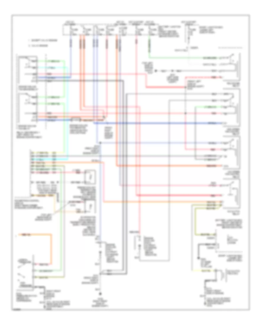
Manual A/C Wiring Diagram (2 of 2) for Ford Taurus SEL 2005
List of elements for Manual A/C Wiring Diagram (2 of 2) for Ford Taurus SEL 2005:
- (3.0l 24-vlv) (3.0l 12-vlv)
- (3.0l, 24-valve: right rear side of engine compartment) g102
- (front left side of engine compt) s140
- (front right
- (right front side of engine) s113
- (top left rear side of engine compt)
- (top left side of engine compt) g107
- (under left side of dash)
- 3.0l 2v engine
- 87a
- A/c clutch diode
- A/c clutch field coil
- A/c clutch relay
- Battery junction box (front center of engine compartment, behind radiator)
- Battery junction box (front center of engine compt, behind radiator)
- C2280a
- C2280c
- Dual pressure switch (behind a/c compressor)
- Engine coolant temperature (ect) sensor (on rear of engine block, near thermostat)
- Engine cooling fan 1 (in front of engine compt, behind radiator)
- Engine cooling fan 2 (in front of engine compt, behind radiator)
- Engine cooling fan brake relay
- Engine cooling fan relay
- Engine cooling fan resistor (near electric cooling fans)
- Evaporator discharge air temperature sensor (early production) (behind center of dash, near glove box)
- Except 3.0l 2v engine
- Fuse 10a
- Fuse 15a
- Fuse 20a
- Fuse 2a
- Fuse 30a
- Fuse 40a
- G105 (right front side of engine compt)
- G202 (at base of left "a" pillar)
- High pressure
- High speed fan control relay
- Hot at all times
- Hot in start or run
- Low speed fan control relay
- Normal pressure
- Pcm power relay
- Powertrain control module (right rear corner of engine compartment)
- Rear side of engine compartment) g102
- Red
- Relay center box 1 (left front of engine compartment)
- S113 (right front side of engine)
- S133
- S137 (left side of engine compt)
- S141 (front right side of engine compt)
- S142
- S144 (front right side of engine compt)
- Side of engine compt)
- Smart junction box
- Smart junction box (under left side of dash)