AIR CONDITIONING
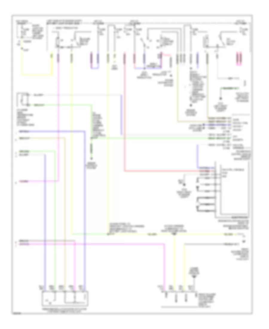
Automatic A/C Wiring Diagram (1 of 2) for Ford Taurus X Limited 2008

List of elements for Automatic A/C Wiring Diagram (1 of 2) for Ford Taurus X Limited 2008:
- (behind left center of dash) in-vehicle temperature sensor
- (in dash, above glove box)
- (in main harness, near breakout to passenger air bag module)
- (lower left side of hvac unit) evaporator discharge air temperature sensor
- (under center console)
- Ambient air temperature sensor (behind center of front bumper)
- Ambient temp sens
- Auto- lamp sens in
- Autolamp/sunload sensor
- Aux blwr pot
- Aux blwr spd rly 1
- Aux blwr spd rly 2
- Aux blwr spd rly 3
- Aux mode door act fdbk
- Aux mode door ccw
- Aux mode door cw
- Aux temp door act fdbk
- Aux temp door ccw
- Aux temp door cw
- Aux temp pot
- Auxiliary a/c circuit
- C2280a
- C2280b
- C228a
- C228b
- Cbp37
- Ch112
- Ch113
- Ch114
- Ch122
- Ch123
- Ch207
- Ch208
- Ch212
- Ch213
- Ch228
- Ch229
- Ch238
- Ch239
- Ch242
- Ch243
- Ch244
- Ch245
- Chs04
- Chs09
- Chs13
- Chs14
- Chs29
- Chs30
- Computer data lines system
- Defogger system
- Defrost request
- Driver temperature blend door actuator (left side of hvac unit)
- Drv htd seat hi status
- Drv htd seat lo status
- Drv htd seat req
- Drv sun load
- Drv temp act fdbk
- Drv temp door ccw
- Drv temp door cw
- Evap temp sens
- Front blower rly
- Fuse 10a
- G202
- Gd111
- Gnd
- Hot at all times
- Hot in run or start
- Hvac module (datc) (behind center of dash)
- Incar temp sens
- Lh111
- Mode 1 actr fdbk
- Mode door 1 ccw
- Mode door 1 cw
- Mode door actuator (left side of hvac unit)
- Ms can+
- Ms can-
- Pass htd seat hi status
- Pass htd seat lo status
- Pass htd seat req
- Pass sun load
- Pass temp act fdbk
- Pass temp door ccw
- Pass temp door cw
- Passenger temperature blend door actuator (under right side of dash)
- Recirc act fdbk
- Recirc ccw
- Recirc cw
- Return
- Rh111
- S201
- S202 (in main harness, near breakout to passenger air bag module)
- Sbp15
- Seats system
- Smart junction box (sjb) (under left side of dash)
- Solid state
- Variable blwr ctrl
- Vbatt
- Vdb06
- Vdb07
- Vh101
- Vh406
- Vh407
- Vh411
- Vh414
- Vh416
- Vh417
- Vh436
- Vh438
- Vh440
- Vha09
- Vha15
- Vha17
- Vha18
- Vpwr
- Vref
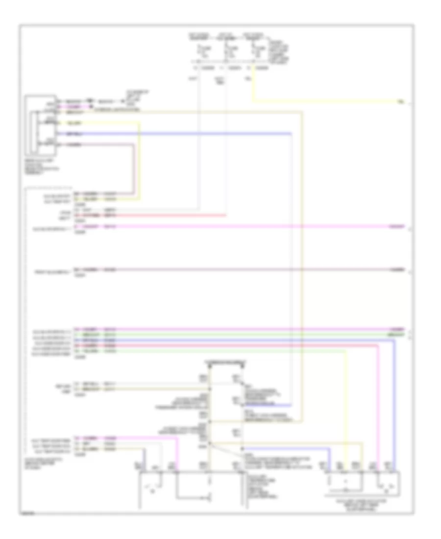
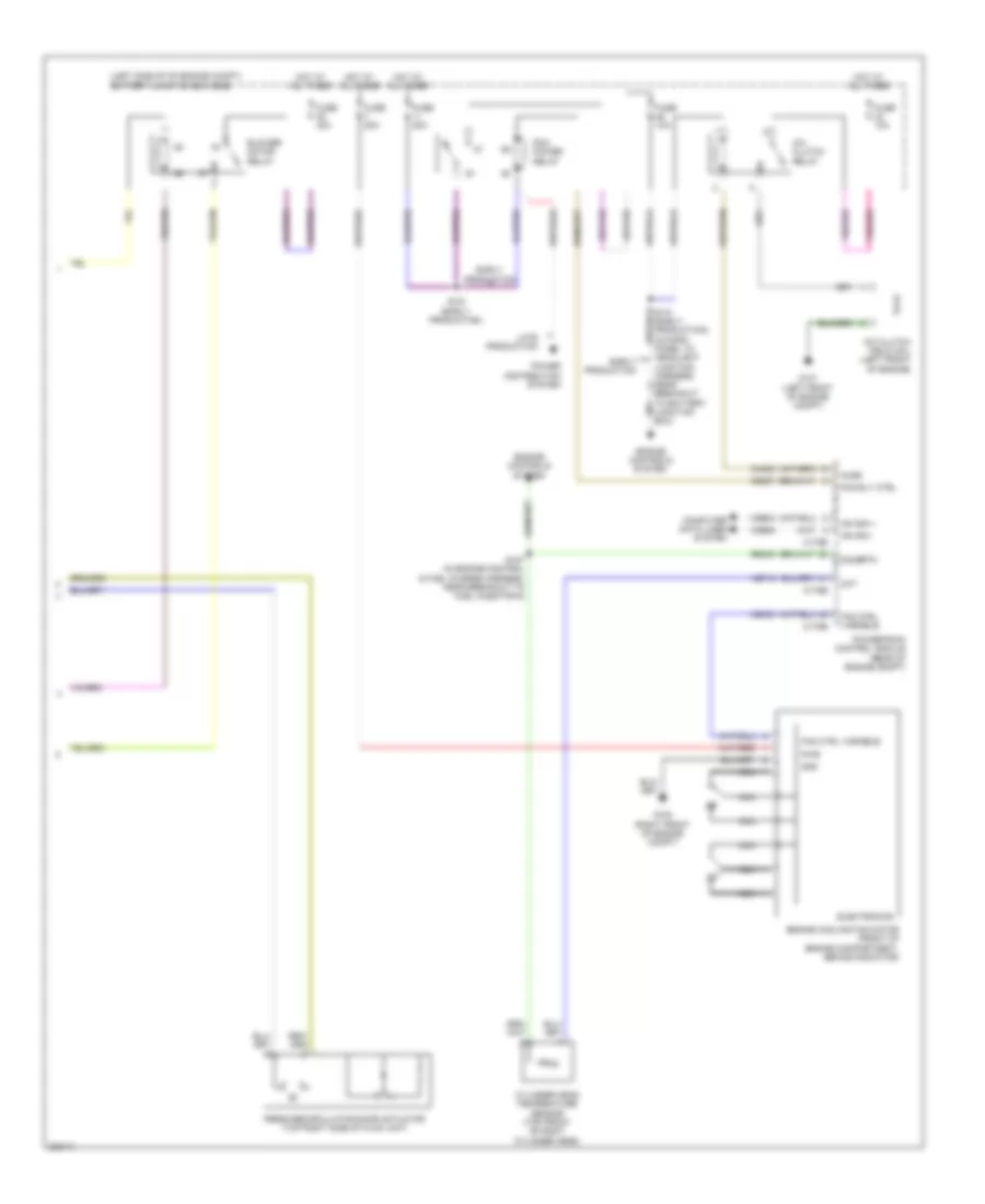
Automatic A/C Wiring Diagram (2 of 2) for Ford Taurus X Limited 2008
List of elements for Automatic A/C Wiring Diagram (2 of 2) for Ford Taurus X Limited 2008:
- (in dash panel to headlight junction harness, near breakout to battery junction box) s140
- (in engine control & fuel charge harness, near breakout to fuel injector 6) s127
- (in main harness, in breakout to front blower motor) s262
- (left side of of engine compt) battery junction box (bjb)
- (not used)
- (under center console) g202
- 10a
- A/c clutch field coil (left front of engine)
- A/c clutch relay
- Accr
- Blower motor relay
- C175b
- C175e
- C2280e
- Ce237
- Ch302
- Cht
- Computer data lines system
- Cylinder head temperature sensor (top front of right cylinder head)
- E-sigrtn
- Early production
- Electronics
- Engine controls system
- Engine cooling fan motor (front of engine compartment, behind radiator)
- Fan ctrl variable
- Fresh/recirculation door actuator (top right side of hvac unit)
- Front blower motor (lower right side of hvac unit)
- Front blower motor speed controller (lower right side of hvac unit)
- Fuse
- Fuse 10a
- Fuse 40a
- Fuse 50a
- Fuse 5a
- G100 (right front of engine compt)
- G101 (left front of engine compt)
- Gnd
- Hot at all times
- Hot in run or acc
- Hs can +
- Hs can -
- Late production
- Motor +
- Motor -
- Nca
- Pcm power relay
- Pcm rly ctrl
- Power distribution system
- Powertrain control module (rear of engine compt)
- Pwm
- Pwr
- Re405
- S141 (early production) (in dash panel to headlight junction harness, near breakout to battery junction box)
- S151 (early production)
- S167
- Smart junction box (sjb) (under left side of dash)
- Vdb04
- Vdb05
- Ve712
- Vec03
Auxiliary A/C Wiring Diagram (1 of 2) for Ford Taurus X Limited 2008
List of elements for Auxiliary A/C Wiring Diagram (1 of 2) for Ford Taurus X Limited 2008:
- (at base of left "c" pillar) g302
- Automatic a/c circuit
- Aux blower
- Aux blwr pot
- Aux blwr spd rly 1
- Aux blwr spd rly 2
- Aux blwr spd rly 3
- Aux mode door ccw
- Aux mode door cw
- Aux mode door fdbk
- Aux temp
- Aux temp door ccw
- Aux temp door cw
- Aux temp door fdbk
- Aux temp pot
- Auxiliary mode actuator (behind left rear quarterpanel)
- Auxiliary temperature actuator (behind left rear quarterpanel)
- Auxiliary temperature actuator)
- C2280a
- C2280b
- C2280e
- C228a
- C228b
- Cbp37
- Ch112
- Ch113
- Ch114
- Ch123
- Ch242
- Ch243
- Ch244
- Ch245
- Front blower rly
- Fuse 10a
- Fuse 5a
- Gnd
- Hot at all times
- Hot in run or acc
- Hot in run or start
- Hvac module (datc) (behind center of dash)
- Illum
- Interior lights system
- Lh111
- Rear auxiliary function selector switch assembly
- Return
- Rh111
- S201 (in main harness, near breakout to passenger air bag module)
- S202 (in main harness, near breakout to passenger air bag module)
- S319 (in body main harness, near breakout to c3007)
- S392
- S911
- Sbp15
- Smart junction box (sjb) (under left side of dash)
- Vbatt
- Vha09
- Vha15
- Vha17
- Vha18
- Vpwr
- Vref
Auxiliary A/C Wiring Diagram (2 of 2) for Ford Taurus X Limited 2008
List of elements for Auxiliary A/C Wiring Diagram (2 of 2) for Ford Taurus X Limited 2008:
- (in air conditioner blower motor harness, in breakout to auxiliary blower motor) s396
- (in air conditioner blower motor harness, near breakout to auxiliary relay box 1) s394
- (in air conditioner blower motor harness, near breakout to auxiliary relay box 1) s395
- (not used)
- Auxiliary blower motor (behind left rear quarterpanel)
- Auxiliary blower motor resistor assembly (left rear corner of vehicle)
- Auxiliary relay box 1 (behind left rear quarterpanel)
- Auxiliary relay box 2 (behind left rear quarterpanel)
- Auxiliary relay box 3 (behind left rear quarterpanel)
- Battery junction box (bjb) (left side of of engine compt)
- Blower motor relay
- Front blower motor (lower right side of hvac unit)
- Front blower motor speed controller (w/ automatic a/c) (lower right side of hvac unit)
- Fuse 30a
- Fuse 40 (early production) 10a
- Fuse 40a
- G302 (at base of left "c" pillar)
- Hot at all times
- S140 (early production) (in dash panel to headlight junction harness, near breakout to battery junction box)
- S167
- S262 (in main harness, in breakout to front blower motor)
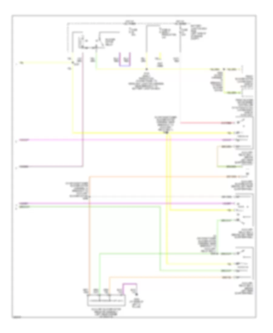
Manual A/C Wiring Diagram (1 of 2) for Ford Taurus X Limited 2008
List of elements for Manual A/C Wiring Diagram (1 of 2) for Ford Taurus X Limited 2008:
- (in main harness, near breakout to passenger air bag module)
- (lower left side of hvac unit) evaporator discharge air temperature sensor
- (under center console) g202
- Blower gnd
- Blower motor resistor (lower right side of hvac unit)
- Blower sw hi
- Blower sw med hi
- Blower sw med lo
- C2280a
- C2280b
- C2280e
- C2357a
- C2357b
- Cbp37
- Ch122
- Ch123
- Ch207
- Ch208
- Ch228
- Ch229
- Ch238
- Ch239
- Ch426
- Ch428
- Ch429
- Computer data lines system
- Defogger system
- Defrost request
- Driver temperature blend door actuator (left side of hvac unit)
- Drv temp door ccw
- Drv temp door cw
- Drv temp door fdbk
- Evap temp sens
- Front blower motor (lower right side of hvac unit)
- Front blower rly
- Fuse 10a
- Fuse 5a
- G202 (under center console)
- Gd111
- Gnd
- Hot at all times
- Hot in run or acc
- Hot in run or start
- Hvac module (emtc) (behind center of dash)
- Lh111
- Mode door 1 ccw
- Mode door 1 cw
- Mode door 1 fdbk
- Mode door actuator (left side of hvac unit)
- Ms can +
- Ms can -
- Recirc door cw
- Recirc door cww
- Return
- Rh111
- S167
- S201
- S202 (in main harness, near breakout to passenger air bag module)
- S263 (in main harness, in breakout to front blower motor)
- Sbp15
- Smart junction box (sjb) (under left side of dash)
- Thermal limiter
- Vbatt
- Vdb06
- Vdb07
- Vh406
- Vh436
- Vh440
- Vpwr
- Vref
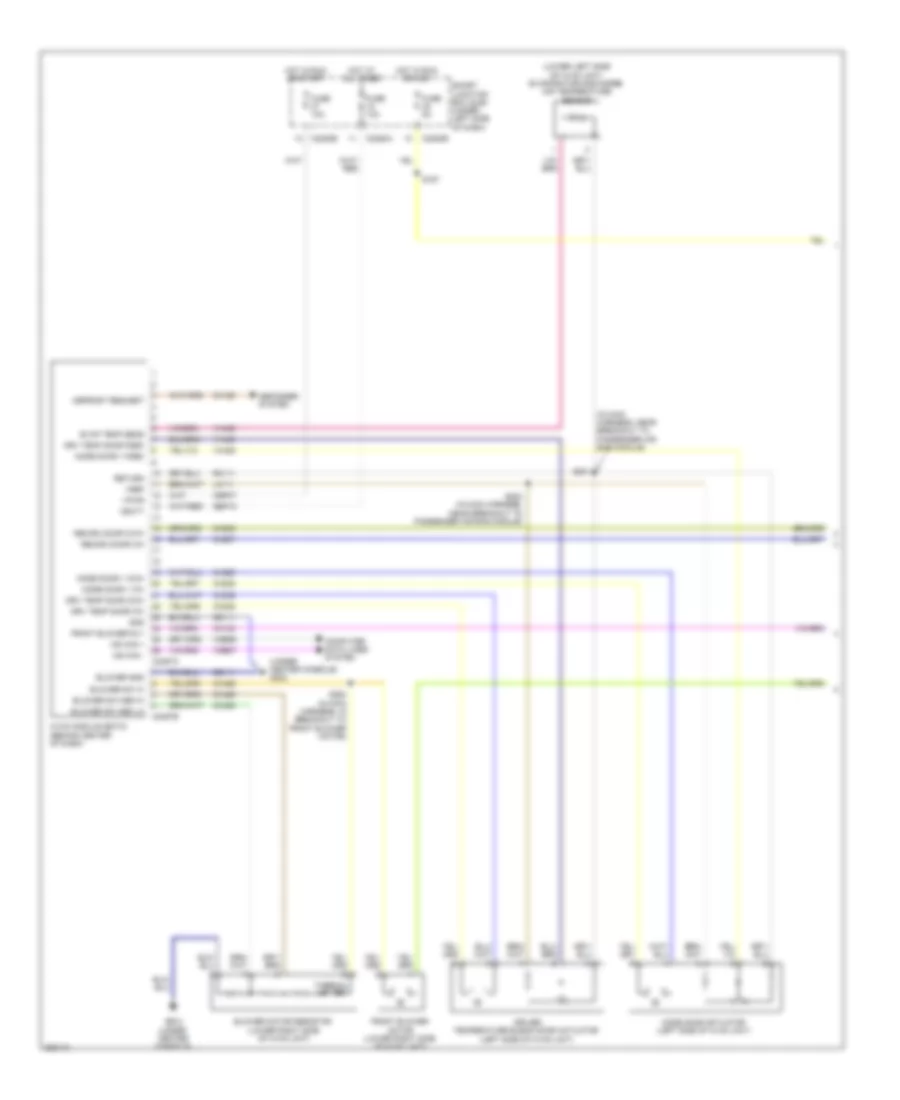
Manual A/C Wiring Diagram (2 of 2) for Ford Taurus X Limited 2008
List of elements for Manual A/C Wiring Diagram (2 of 2) for Ford Taurus X Limited 2008:
- (left side of of engine compt) battery junction box (bjb)
- A/c clutch field coil (left front of engine)
- A/c clutch relay
- Accr
- Blower motor relay
- C175b
- C175e
- Ce237
- Ch302
- Cht
- Computer data lines system
- Cylinder head temperature sensor (top front of right cylinder head)
- E-sigrtn
- Early production
- Electronics
- Engine controls system
- Engine cooling fan motor (front of engine compartment, behind radiator)
- Fan ctrl variable
- Fresh/recirculation door actuator (top right side of hvac unit)
- Fuse 10a
- Fuse 40a
- Fuse 50a
- G100 (right front of engine compt)
- G101 (left front of engine compt)
- Gnd
- Hot at all times
- Hs can +
- Hs can -
- Late production
- Nca
- Pcm power relay
- Pcm rly ctrl
- Power distribution system
- Powertrain control module (rear of engine compt)
- Pwr
- Re405
- S127 (in engine control & fuel charge harness, near breakout to fuel injector 6)
- S141 (early production) (in dash panel to headlight junction harness, near breakout to battery junction box)
- S151 (early production)
- Vdb04
- Vdb05
- Ve712
- Vec03