AIR CONDITIONING
Automatic A/C Wiring Diagram (1 of 2) for Ford Thunderbird 2002

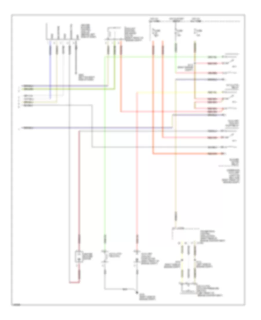
List of elements for Automatic A/C Wiring Diagram (1 of 2) for Ford Thunderbird 2002:
- (center of dash)
- Battery
- C228a
- C228b
- C270a
- Central junction box (behind lower left side of dash)
- Computer data lines system
- Cool air bypass actuator (behind right center of dash, on hvac assembly)
- Data link (+)
- Data link (-)
- Defrost mode actuator (behind center of dash, on hvac assembly)
- Electronic automatic temperature control (eatc) module (behind center of dash)
- Evaporator discharge air temperature sensor (behind center of dash)
- Floor mode actuator (behind left center of dash, on hvac assembly)
- Fresh/recirculate door actuator (behind center of dash, on hvac assembly)
- Fuse 10a
- Fuse 5a
- G203 (bottom right side of dash)
- Hot at all times
- Hot in run
- Ign
- In-vehicle temperature sensor (behind center of dash)
- Left discharge temperature sensor (left side of dash)
- Outside temperature sensor (right front of engine compt)
- Panel mode actuator (behind right side of dash, on hvac assembly)
- Rear defogger system
- Right discharge air temperature sensor (right side of dash)
- S210
- S212 (right side of dash)
- S213 (right side of dash)
- S225 (center of dash)
- Sensor return
- Sensor signal
- Sensor signal return
- Sensor voltage
- Signal 2
- Sunload sensor (top of dash, above glove box)
- Switched (batt/gnd/open)
- Switched gnd
Automatic A/C Wiring Diagram (2 of 2) for Ford Thunderbird 2002
List of elements for Automatic A/C Wiring Diagram (2 of 2) for Ford Thunderbird 2002:
- A/c clutch cycling pressure switch (left front of engine compartment)
- A/c clutch field coil
- A/c clutch relay
- Auxiliary coolant pump motor (right front of engine compt)
- Auxiliary coolant pump relay
- Blower ctrl
- Blower motor relay
- C175a
- Coolant control solenoid valve (right front of engine compt)
- Fuse 10a
- Fuse 15a
- Fuse 30a
- G102 (right side of engine compt)
- G203 (bottom right side of dash)
- Gnd
- Heater blower control module (behind left side of dash)
- Heater blower motor
- Hot at all times
- Hot in start or run
- Powertrain control module (pcm) (right rear of engine compartment)
- S104 (right side of engine compt)
- S112 (right engine compt)
- S114 (left side of engine compt)
- Sig return
- Underhood auxiliary junction box (ajb) (right front of engine compt)
- Vref