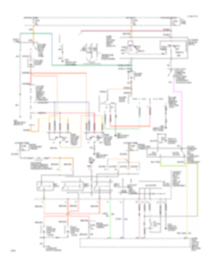
AIR CONDITIONING
A/C Wiring Diagram for Ford Windstar 1995
List of elements for A/C Wiring Diagram for Ford Windstar 1995:
- (behind left
- (front of transaxle on stud)
- A/c clutch coil
- A/c clutch control
- A/c clutch cycling pressure switch (right rear of engine compartment on accumulator)
- A/c high pressure cutout/ fan switch (lower right rear of engine compartment)
- A/c-heater
- Aux ctrl
- Auxiliary blower motor
- Auxiliary blower motor relay (in i/p fuse panel)
- Auxiliary blower motor resistor assembly (behind panel, left of rear seat)
- B 60a
- Blend door actuator (behind right side of i/p)
- Blower motor
- Blower motor resistor (behind right side of i/p)
- Blower motor switch
- C 1995 vftc
- Clutch switch
- Constant control relay module (left front of engine compartment)
- Cooling fan dropping resistor (lower right front of engine compartment)
- Cowl panel)
- Def
- Def/flr
- Edf relay
- Edf relay control
- Engine compartment fuse box
- Fan switch
- Flr
- Fuel pump relay
- Fuse
- Fuse 10a
- Fuse 30a
- Fuse w 10a
- G100 (lower left front of engine)
- G130
- G130 (front of transaxle on stud)
- G200
- G200 (behind left cowl panel)
- G201 (behind right side of i/p)
- H 40a
- Hedf 1 relay
- Hedf 2 relay
- Hot at all times
- Hot in acc or run
- Hot in run
- I/p fuse panel
- Left electric cooling fan motor
- Max
- Nca
- Norm
- Off
- Pan/flr
- Panel
- Pcm power relay
- Power- train control module (behind right side of i/p)
- Rear auxiliary blower motor switch (front)
- Rear auxiliary blower motor switch (rear)
- Red
- Red/pnk
- Right electric cooling fan motor
- Selector switch
- Solid state
- Temperature control potentiometer
 English