AIR CONDITIONING
A/C Wiring Diagram for Mercury Capri XR2 1994

List of elements for A/C Wiring Diagram for Mercury Capri XR2 1994:
- (near thermostat housing)
- 15a
- A/c clutch cycling pressure switch (left rear of engine compartment)
- A/c clutch relay (left rear corner of engine compartment)
- A/c compressor clutch coil
- A/c control module (behind lower right side of i/p)
- A/c switch
- Air cond fuse 15a
- Blower motor
- Blower motor control switch
- Blower motor resistor (behind glove box)
- C 1995 vftc
- C220
- C223
- C283
- C284
- C298
- Condenser fan motor
- Condenser fan relay (left rear corner of engine compartment)
- Cooler in-line fuse (left rear corner of engine compartment)
- Cooling fan fuse 25a
- Cooling fan motor
- Cooling fan relay (left front of engine compartment)
- Cooling fan temperature switch
- Electrical load control module (below center of i/p)
- G100 (left side of engine compartment)
- G202 (attached to cowl panel, be- hind instrument cluster)
- G202 (attached to cowl panel, behind instrument cluster)
- Heater circuit breaker 30a
- Hot in run or start
- Interior fuse panel/ joint box
- Interior lights system
- Nca
- Off
- Powertrain control module (below center of i/p)
- Red
- Thermistor (in evaporator housing)
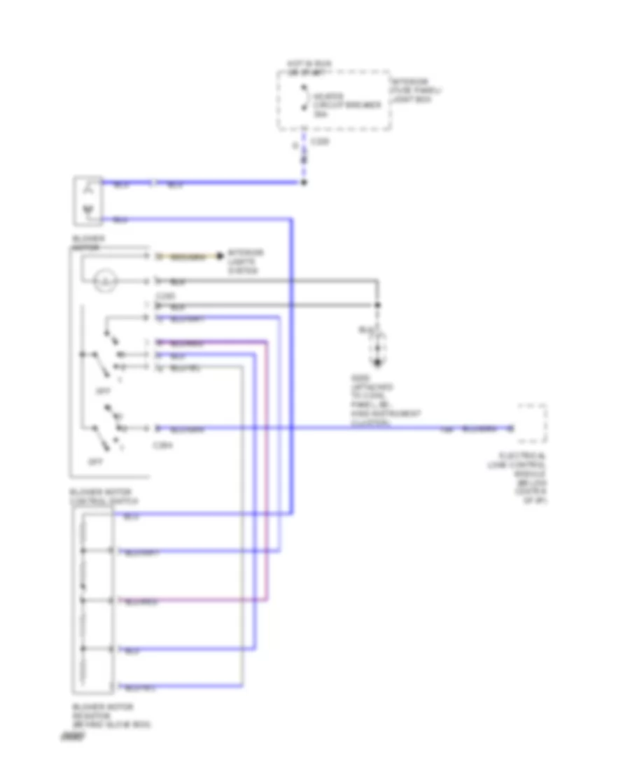
Heater Wiring Diagram for Mercury Capri XR2 1994
List of elements for Heater Wiring Diagram for Mercury Capri XR2 1994:
- Blower motor
- Blower motor control switch
- Blower motor resistor (behind glove box)
- C220
- C283
- C284
- Electrical load control module (below center of i/p)
- G202 (attached to cowl panel, be- hind instrument cluster)
- Heater circuit breaker 30a
- Hot in run or start
- Interior fuse panel/ joint box
- Interior lights system
- Off