AIR CONDITIONING
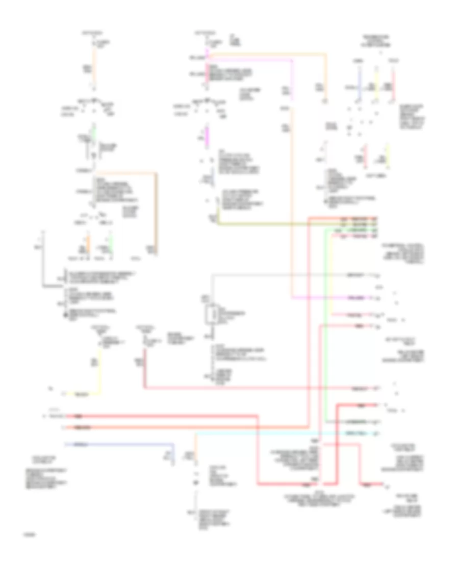
Automatic A/C Wiring Diagram for Mercury Grand Marquis LS 1999

List of elements for Automatic A/C Wiring Diagram for Mercury Grand Marquis LS 1999:
- (behind right kick panel, near door sill) g201
- (front of right front fender apron, right side of battery) g102
- (in engine harness, near breakout to in-line connector, left rear corner of engine compartment, rear of wheelwell) s129
- (in main harness, near breakout to day/night amplifier sensor) s226
- (not used)
- (rear center of engine) g106
- 87a
- A/c clutch cycling pressure switch (right rear of engine compartment, on a/c accumulator)
- A/c clutch output
- A/c compressor clutch coil
- A/c high pressure cut out switch (right side of engine compartment, near fuse box)
- A/c wot cutout relay
- Amb temp sens input
- Ambient temperature sensor (center front of vehicle, on front of upper radiator support)
- Battery
- Blend door (cool)
- Blend door (heat)
- Blend door actuator (behind right side of dash, top of a/c plenum)
- Blend door pot gnd
- Blend dr feedback
- Blower motor
- Blower motor speed controller (top right center of firewall, on evaporator assembly)
- Blower mtr output
- Blower speed fback
- C227
- C228
- Circuit breaker 17 30a
- Computer data lines system
- Connector behind right side of dash) s204
- Cooling fan (front of engine compartment)
- Cooling fan high relay
- Cooling fan low relay
- Data
- E/m converter
- Electronic automatic temperature control (eatc) module (behind center of dash)
- Engine compartment fuse box
- Engine compartment fuse box (right front of engine compartment, behind battery)
- Front panel illum
- Fuse 13 50a
- Fuse 15a
- Fuse 30a
- Ground
- High current relay center (right rear of engine compartment)
- Hot at all times
- Hot at all times
- Hot in run
- I/p fuse panel
- In car temp sens
- In-car temperature sensor (behind top center of dash)
- Inst illumination
- Instrument cluster (digital)
- Interior lights system
- Near door sill) g203
- Pcm power relay
- Power
- Powertrain control module (pcm) (behind left side of dash, on left side of firewall)
- Red
- Reference voltage
- Relay center (left side of engine compartment)
- Relay signal
- S116 (in dash panel to headlamp junction harness, near breakout to in-line connector, inside front of right front fender)
- S139
- S157 (in engine harness, near breakout to g102)
- S206 (in main harness, near breakout to glove box lamp)
- S227 (in main harness, in breakout to lighting control module)
- S251 (in main harness, in breakout to eatc)
- Sensor ground
- Sun load sensor (top right side of dash, above glove box)
- Sunload sens input
Manual A/C Wiring Diagram for Mercury Grand Marquis LS 1999
List of elements for Manual A/C Wiring Diagram for Mercury Grand Marquis LS 1999:
- (behind right kick panel, near door sill) g201
- (behind right kick panel, near door sill) g203
- (center rear of engine) g106
- (front of right front fender apron, right side of battery) g102
- (not used)
- 87a
- A/c clutch cycling pressure switch (right rear of engine compartment, on a/c accumulator)
- A/c compressor clutch coil
- A/c high pressure cut out switch (right side of engine compartment, near fuse box)
- A/c wot cutout relay
- A/c-heater mode switch
- Blend door actuator (behind right side of dash, top of a/c plenum)
- Blower motor
- Blower motor resistor assembly (top right center of firewall, on evaporator assembly)
- Blower motor switch
- Circuit breaker 17 30a
- Cold
- Cooling fan (front of engine compartment)
- Cooling fan high relay
- Cooling fan low relay
- Def
- Engine compartment fuse box
- Engine compartment fuse box (right front of engine compartment, behind battery)
- Floor
- Fuse 13 50a
- Fuse 5 15a
- Fuse 9 30a
- High current relay center (right rear of engine compartment)
- Hot at all times
- Hot in run
- I/p fuse panel
- Lamp)
- Max a/c
- Med hi
- Med lo
- Mix
- Norm a/c
- Off
- Pcm power relay
- Powertrain control module (pcm) (behind left side of dash, on left side of firewall)
- Red
- Relay center (left side of engine compartment)
- S116 (in dash panel to headlamp junction harness, near breakout to g102, right side of battery)
- S129 (in engine harness, near breakout to in line connector, left rear corner of engine compartment)
- S139
- S157 (in engine harness, near breakout to a/c compressor clutch coil)
- S206 (in main harness, near breakout to glove box lamp)
- S226 (in main harness, near breakout to day/night sensor amplifier)
- S239 (in main harness, near breakout to in-line connector, right rear of engine compartment)
- Solid state
- Temperature control potentiometer
- Vent
- Warm