AIR CONDITIONING
Automatic A/C Wiring Diagram (1 of 2) for Mercury Grand Marquis LS 2006

List of elements for Automatic A/C Wiring Diagram (1 of 2) for Mercury Grand Marquis LS 2006:
- A/c output
- Amb temp sens input
- Ambient air temperature sensor (on front of upper radiator support)
- Battery
- Battery junction box (bjb) (in right front of engine compt, behind battery)
- Blend door cool
- Blend door heat
- Blower
- Blower motor high
- Blower motor relay
- C228a
- C228b
- Central junction box (cjb) (below dash, left of steering column)
- Computer data lines system
- Electronic automatic temperature control (eatc) module (behind center of dash)
- Front blower motor (at right rear of engine compt)
- Front blower motor speed controller (at rear of engine compt)
- Fuse 10a
- Fuse 15a
- Fuse 40a
- G109 (at front of right fender)
- G203 (behind right kick panel)
- Ground
- Hot at all times
- Hot in start
- In car temp sens
- In-vehicle temperature sensor (behind center of dash)
- Instrument illum
- Interior lights system
- Pot feed
- Pot feedback
- Pot rtn
- Run
- S121 (in dash panel to headlamp junction harness, near breakout to battery junction box)
- S203 (in main body wiring harness, near breakout to instrument cluster)
- S207 (in main wiring harness, near breakout to rear window defrost switch)
- Scp bus (+)
- Scp bus (-)
- Sens rtn
- Steering wheel ctrl
- Sunload sens input
- Variable volt dim
- Vbc hbr
- Vbc input
- Vbc output
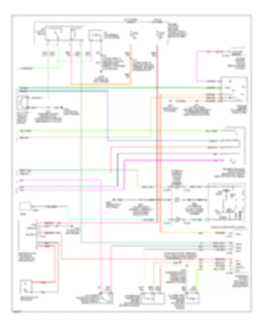
Automatic A/C Wiring Diagram (2 of 2) for Mercury Grand Marquis LS 2006
List of elements for Automatic A/C Wiring Diagram (2 of 2) for Mercury Grand Marquis LS 2006:
- (at base of steering column) air bag sliding contact
- (in engine control sensor & fuel charge wiring harness, near breakout to cop 4)
- A/c clutch field coil (at right front of engine)
- A/c clutch relay
- A/c compressor clutch diode
- A/c pressure transducer sensor (on right side center of engine)
- Accr
- Accs
- Acpt
- Audio/climate control switch
- Autolamp sensor
- Autolamp sensor (on upper left side of dash)
- Battery junction box (bjb) (in right front of engine compt, behind battery)
- C1048
- C175b
- C175e
- C175t
- C2145a
- C218a
- C218b
- C290a
- Cht
- Cylinder-head temperature sensor (on top left front of engine)
- Engine cooling fan module (left front of engine compt)
- Engine cooling fan motor
- Fan down
- Fan up
- Fc v
- Fuse 15a
- Fuse 50a
- G102 (at front of left fender)
- G109 (at front of right fender)
- G201 (behind right kick panel)
- G203 (behind right kick panel)
- Ground
- Hot at all times
- Hot in start or run
- Lighting control module (behind center of dash)
- Low charge protection switch (at right side of engine compt)
- Patil
- Phone
- Powertrain control module (pcm) (left rear of engine compt)
- Pwr
- Radio
- Red
- Rest
- S111 (in dash panel to headlamp junction harness, left rear of engine compt)
- S121
- S123 (in engine control sensor & fuel charge wiring harness, near breakout to pcm)
- S126
- S157 (in engine control sensor & fuel charge wiring harness, near breakout to c192)
- S201 (in main wiring harness, in breakout to adjustable pedal switch)
- S210 (in main wiring harness, near breakout to passenger air bag deactivation indicator)
- S294 (in steering column control switch jumper harness)
- Sig rtn 1
- Temp down
- Temp up
- Temperature blend door actuator (behind right side of dash, on top of a/c plenum)
- Var spd in
- Vref
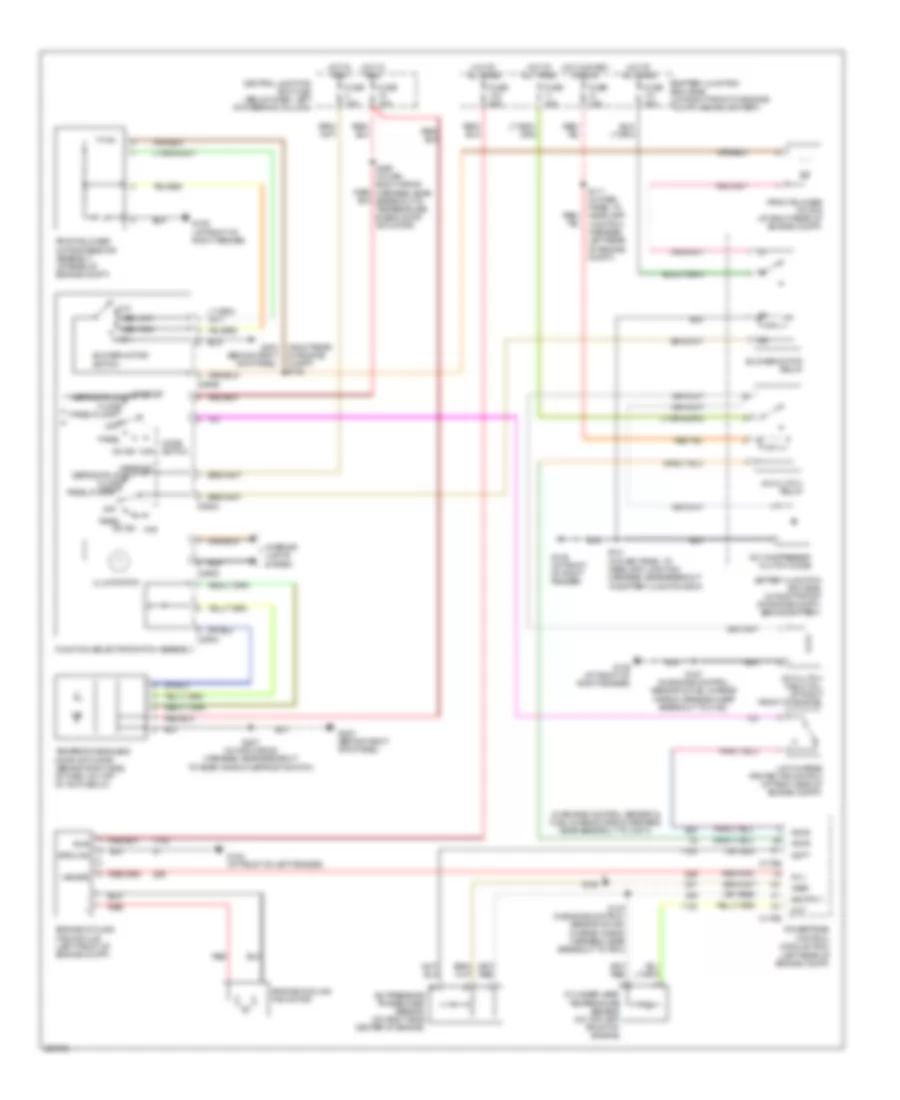
Manual A/C Wiring Diagram for Mercury Grand Marquis LS 2006
List of elements for Manual A/C Wiring Diagram for Mercury Grand Marquis LS 2006:
- (in engine control sensor & fuel charge wiring harness, near breakout to cop 4)
- (left rear of engine compt)
- (right rear of engine compt) s122
- A/c clutch field coil (at right front of engine)
- A/c clutch relay
- A/c compressor clutch diode
- A/c pressure transducer sensor (on right side center of engine)
- A/c sw max
- Accr
- Accs
- Acpt
- Battery junction box (bjb) (in right front of engine compt, behind battery)
- Blower motor relay
- Blower motor switch
- C175b
- C175e
- C294a
- C294b
- C294c
- C294d
- Central junction box (cjb) (below dash, left of steering column)
- Cht
- Cylinder-head temperature sensor (on top left front of engine)
- Defrost
- Defrost defrost/floor
- Defrost/floor
- Engine cooling fan module (left front of engine compt)
- Engine cooling fan motor
- Fc v
- Floor
- Front blower motor (at right rear of engine compt)
- Front blower motor resistor assembly (at rear of engine compt)
- Function selector switch assembly
- Fuse 10a
- Fuse 15a
- Fuse 40a
- Fuse 50a
- G102 (at front of left fender)
- G109 (at front of right fender)
- G203 (behind right kick panel)
- G204 (behind right kick panel)
- Ground
- High
- Hot at all times
- Hot in run
- Hot in start or run
- Illumination
- Interior lights system
- Low
- Low charge protection switch (at right side of engine compt)
- Med high
- Med low
- Mode switch
- Off
- Panel
- Panel/floor
- Powertrain control module (pcm)
- Pwr
- Red
- S111 (in dash panel to headlamp junction harness, left rear of engine compt)
- S121 (in dash panel to headlamp junction harness, near breakout to battery junction box)
- S123 (in engine control sensor & fuel charge wiring harness, near breakout to pcm)
- S126
- S157 (in engine control sensor & fuel charge wiring harness, near breakout to c192)
- S207 (in main wiring harness, near breakout to rear window defrost switch)
- S209 (in main body wiring harness, near breakout to temperature blend door actuator)
- Sig rtn 1
- Temperature blend door actuator (behind right side of dash, on top of a/c plenum)
- Var spd
- Vref