AIR CONDITIONING
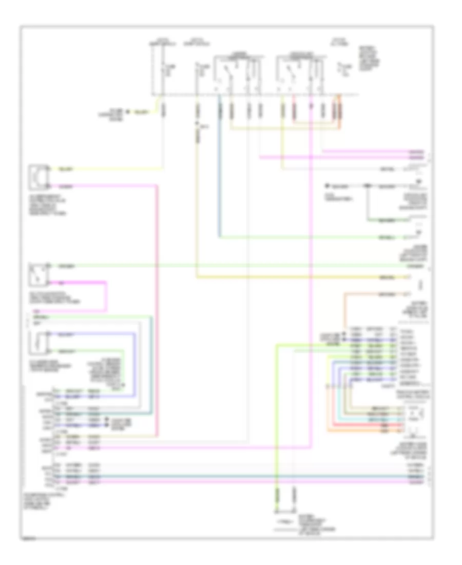
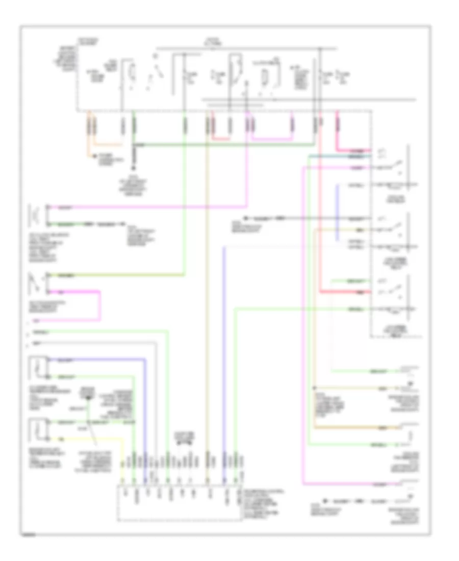
Automatic A/C Wiring Diagram, Except Hybrid (1 of 3) for Mercury Mariner Premier 2008

List of elements for Automatic A/C Wiring Diagram, Except Hybrid (1 of 3) for Mercury Mariner Premier 2008:
- (right side of dash) s225
- 5v vref return
- Ambient temp sens
- Battery junction box (bjb) (left front of engine compt)
- Blower motor control module (right side of dash)
- Blower motor relay
- Blwr ctrl (vbc)
- C2280a
- C2280b
- C2280e
- C2357a
- C2357b
- Cbp37
- Ch122
- Ch123
- Ch207
- Ch208
- Ch212
- Ch213
- Ch228
- Ch229
- Ch238
- Ch239
- Ch402
- Chs29
- Chs30
- Computer data lines system
- Defogger system
- Drv htd seat rly
- Drv sunload sens
- Drv temp act fdbk
- Drv temp dr ccw
- Drv temp dr cw
- Evap temp sens
- Fr blwr relay
- Front blower motor (right side of dash)
- Fuse 10a
- Fuse 40a
- Fuse 5a
- G200 (behind right side of dash)
- G202 (behind left side of dash)
- Gd112
- Gd114
- Gnd
- Hot at all times
- Hot in run or acc
- Hot in run or start
- Hvac (datc)
- In car temp sens
- In-vehicle temperature sensor (left side of dash)
- Lh111
- Logic
- Mode 1 act fdbk
- Mode dr 1 ccw
- Mode dr 1 cw
- Mot+
- Mot-
- Ms can+
- Ms can-
- Pass htd seat rly
- Pass temp act fdbk
- Pass temp dr ccw
- Pass temp dr cw
- Passenger temperature blend door actuator (right side of dash, on hvac assembly)
- Power distribution system
- Pwm
- R-def
- Recirc dr ccw
- Recirc dr cw
- Rh111
- S202
- Sbp15
- Seats system
- Smart junction box (sjb) (below center of dash)
- V batt
- V ign
- V ref 5v
- Vdb06
- Vdb07
- Vh101
- Vh301
- Vh406
- Vh407
- Vh414
- Vh416
- Vh417
- Vh436
- Vh440
- Vh441
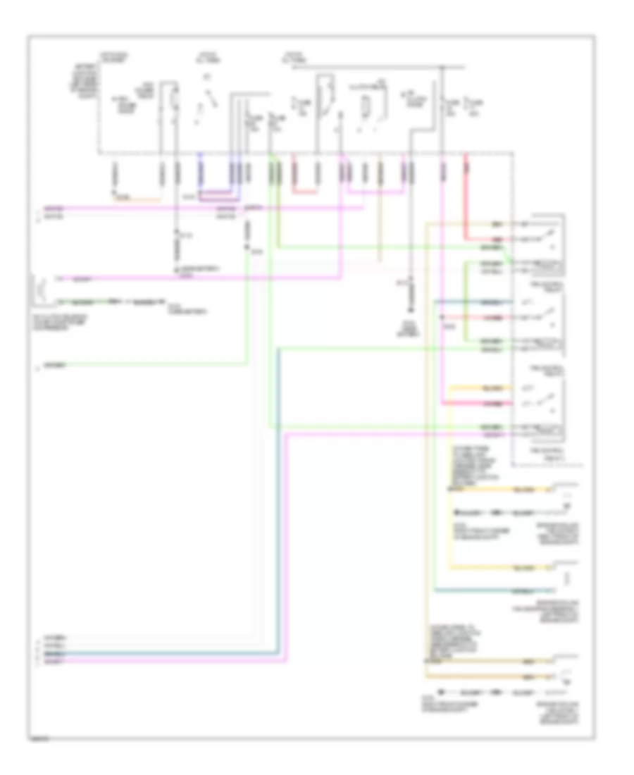
Automatic A/C Wiring Diagram, Except Hybrid (2 of 3) for Mercury Mariner Premier 2008
List of elements for Automatic A/C Wiring Diagram, Except Hybrid (2 of 3) for Mercury Mariner Premier 2008:
- (behind center of dash) s210
- (in air conditioning jumper wiring harness, near c2029) s222
- (in air conditioning wiring harness, near recirculation blend door actuator) s223
- (right front of engine compt) g103
- Ambient air temperature sensor (behind left side of front grille)
- Autolamp/ sunload sensor (center of dash)
- Control solid state
- Driver temperature blend door actuator (right side of dash, on hvac assembly)
- Dual pressure switch (right front of engine compt)
- Evaporator discharge air temperature sensor (right side of dash, near evaporator)
- G202 (behind left side of dash)
- Mode door actuator (right side of dash, on hvac assembly)
- Recirculation blend door actuator (right side of dash, on hvac assembly)
- S202
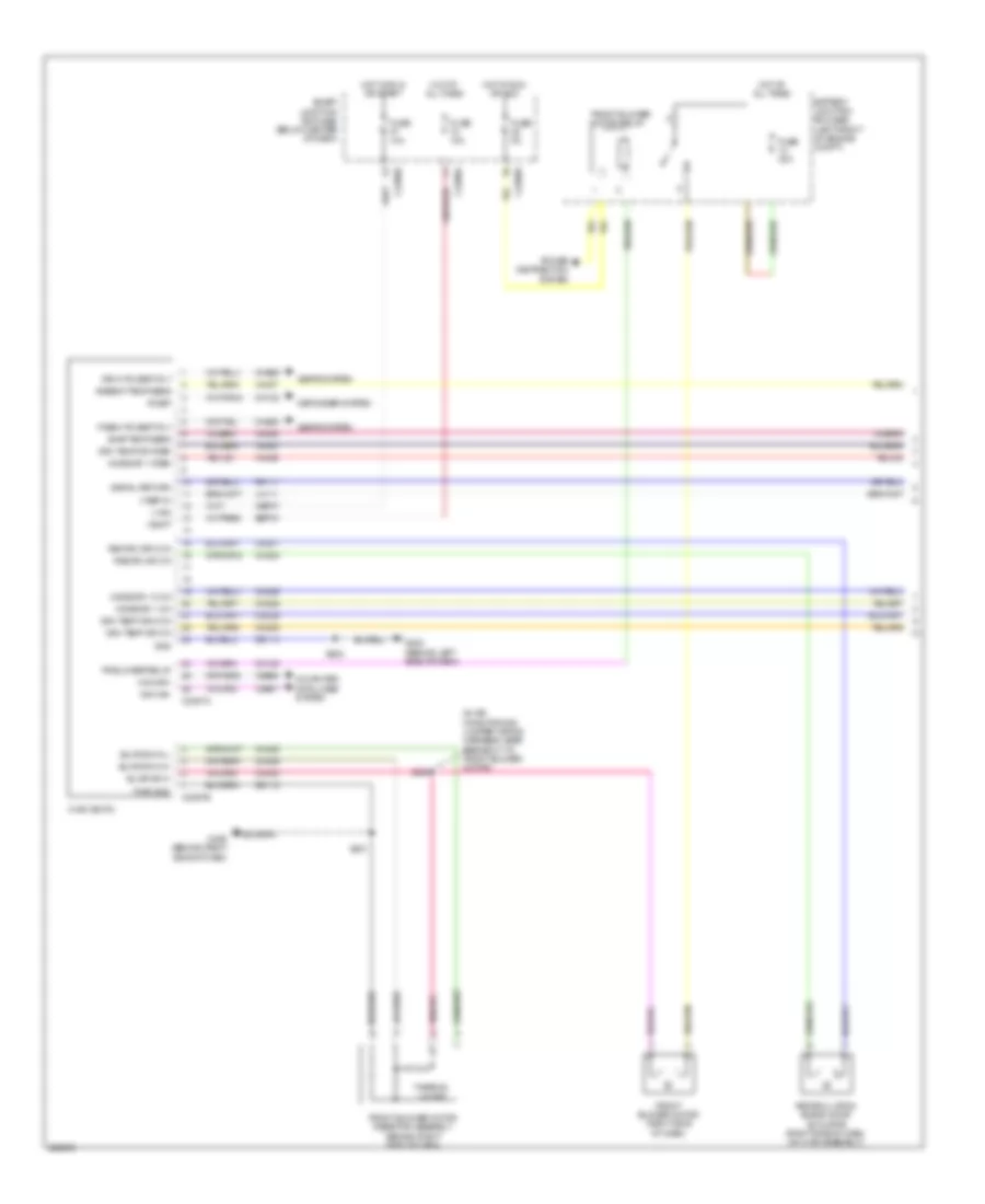
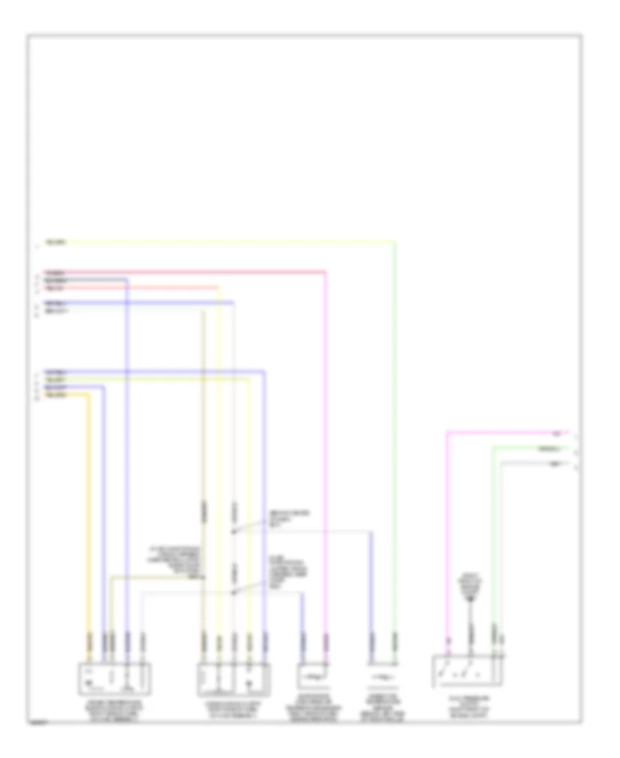
Automatic A/C Wiring Diagram, Except Hybrid (3 of 3) for Mercury Mariner Premier 2008
List of elements for Automatic A/C Wiring Diagram, Except Hybrid (3 of 3) for Mercury Mariner Premier 2008:
- (in engine control sensor & fuel charge wiring harness, before breakout to fuel injector 3)
- (in fuel shut off off solenoid wiring harness, near breakout to fuel injector 6)
- A/c clutch diode (early produ- ction)
- A/c clutch relay
- A/c clutch solenoid (2.3l: right front corner of engine compt) (3.0l: right front side of engine compt)
- A/c cycling switch (right rear of engine compt)
- Accr
- Accs
- Acpsw
- Battery junction box (bjb) (left front of engine compt)
- C175b
- C175e
- Can+
- Can-
- Cec01
- Cec02
- Ch302
- Ch421
- Ch425
- Cht
- Computer data lines system
- Cooling fan relay
- Cooling fan resistor (2.3l) (left front of engine compt)
- Cylinder head temperature sensor (2.3l) (top of engine, on cylinder head)
- Ect
- Engine controls system
- Engine coolant temperature (ect) (3.0l) (rear of engine in water outlet)
- Engine cooling fan motor 1 (front of engine compt)
- Engine cooling fan motor 2 (front of engine compt)
- Fan ctrl
- Fuse 10a
- Fuse 40a
- G102 (right front of engine compt)
- G104 (at left front corner of engine compt, near bjb)
- High speed fan control relay
- Hot at all times
- Hot in run or start
- Low speed fan control relay
- Pcm power diode
- Pcm power relay
- Power distribution system
- Powertrain control module (pcm) (3.0l: in recess on upper center of firewall) (2.3l: rear center of firewall)
- Re405
- Red
- S100
- S102
- S108 (in headlamp jumper wiring harness, near breakout to c139)
- S109
- S118
- S129
- Sigrtne
- Vdb04
- Vdb05
- Ve712
- Ve716
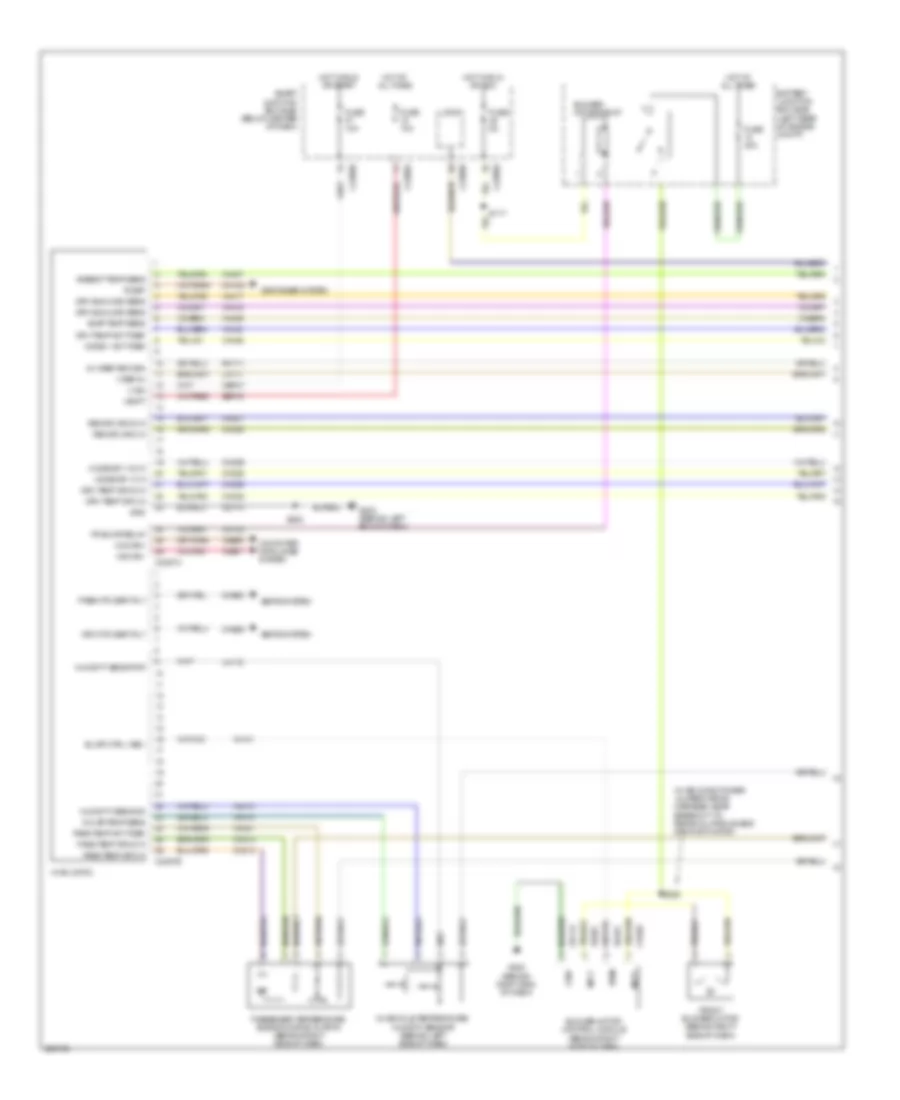
Automatic A/C Wiring Diagram, Hybrid (1 of 4) for Mercury Mariner Premier 2008
List of elements for Automatic A/C Wiring Diagram, Hybrid (1 of 4) for Mercury Mariner Premier 2008:
- (in air conditioner jumper wiring harness, near breakout to recirculation blend door actuator)
- 5v vref return
- Ambient temp sens
- Battery junction box (bjb) (left rear of engine compt)
- Blower motor control module (behind right side of dash)
- Blower motor relay
- Blwr ctrl (vbc)
- C2280a
- C2280b
- C2280e
- C2357a
- C2357b
- Cbp37
- Ch122
- Ch123
- Ch207
- Ch208
- Ch212
- Ch213
- Ch228
- Ch229
- Ch238
- Ch239
- Ch402
- Chs29
- Chs30
- Computer data lines system
- Defogger system
- Drv htd seat rly
- Drv sunload sens
- Drv temp act fdbk
- Drv temp dr ccw
- Drv temp dr cw
- Evap temp sens
- Fr blwr relay
- Front blower motor (behind right side of dash)
- Fuse 10a
- Fuse 40a
- Fuse 5a
- G200 (behind right end of dash)
- G202 (behind left end of dash)
- Gd112
- Gd114
- Gnd
- Hot at all times
- Hot in run or acc
- Hot in run or start
- Humidity sens pwr
- Humidity sens sig
- Hvac (datc)
- In car temp sens
- In-vehicle temperature/ humidity sensor (behind left side of dash)
- Lh111
- Lh115
- Logic
- Mode 1 act fdbk
- Mode dr 1 ccw
- Mode dr 1 cw
- Mot+
- Mot-
- Ms can+
- Ms can-
- Pass htd seat rly
- Pass temp act fdbk
- Pass temp dr ccw
- Pass temp dr cw
- Passenger temperature blend door actuator (behind right side of dash)
- Pwm
- R-def
- Recirc dr ccw
- Recirc dr cw
- Rh111
- S117
- S202
- S225
- Sbp15
- Seats system
- Smart junction box (sjb) (below center of dash)
- V batt
- V ign
- V ref 5v
- Vdb06
- Vdb07
- Vh101
- Vh301
- Vh406
- Vh407
- Vh413
- Vh414
- Vh416
- Vh417
- Vh436
- Vh440
- Vh441
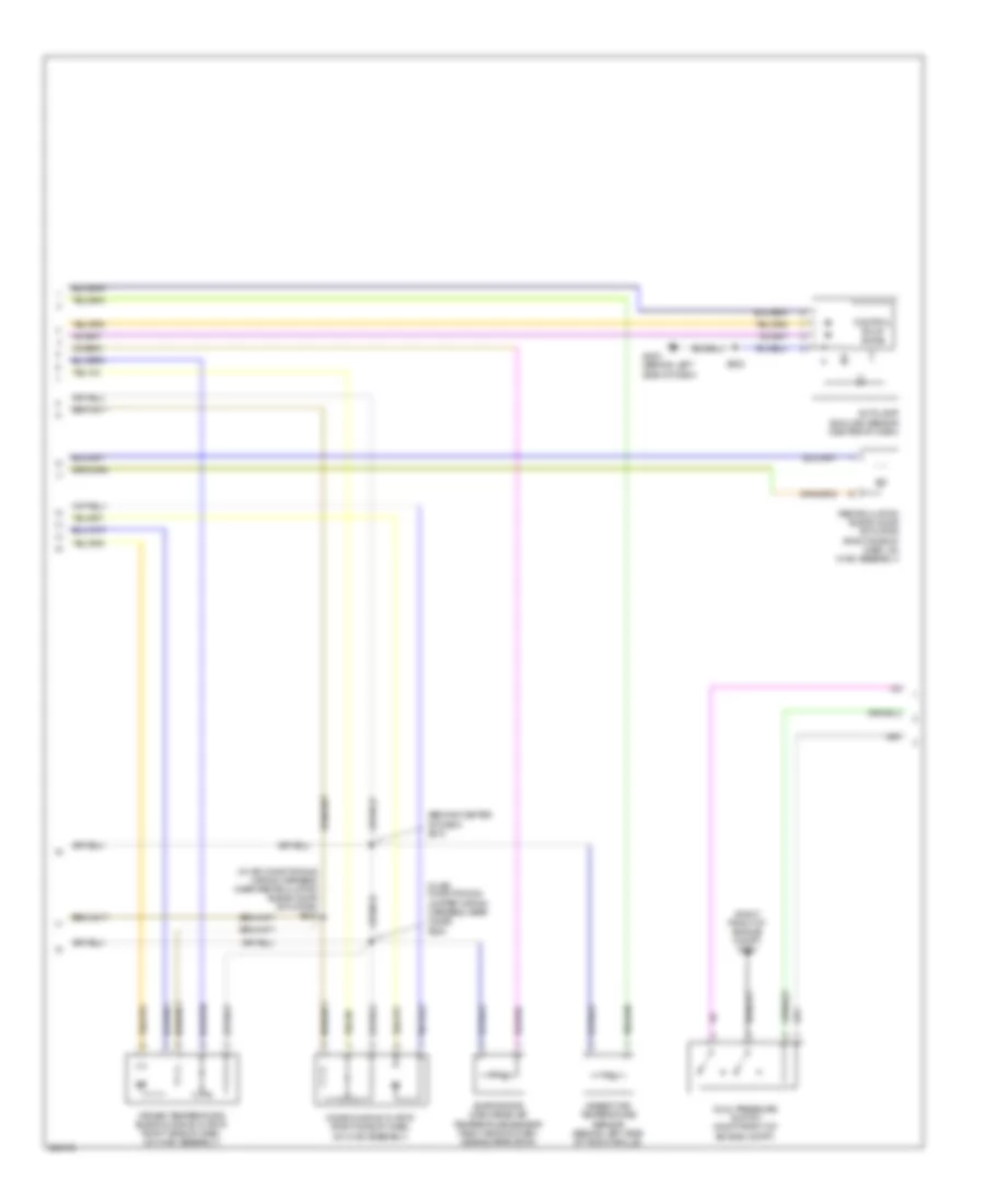
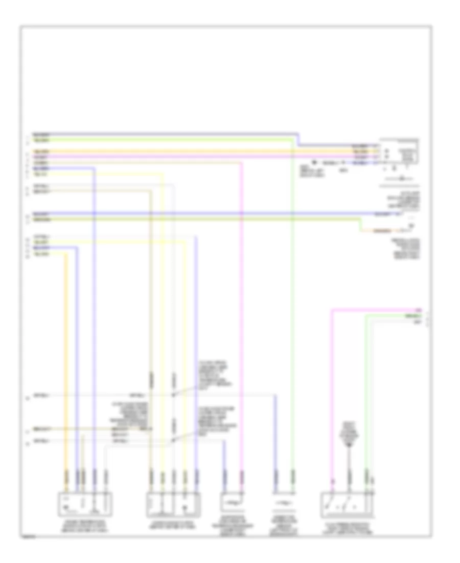
Automatic A/C Wiring Diagram, Hybrid (2 of 4) for Mercury Mariner Premier 2008
List of elements for Automatic A/C Wiring Diagram, Hybrid (2 of 4) for Mercury Mariner Premier 2008:
- (in air conditioner jumper wiring harness, near breakout to temperature blend door actuator) s222
- (in air conditioner jumper wiring harness, near breakout to temperature blend door actuator) s223
- (in main wiring harness, near breakout to in-vehicle temperature/ humidity sensor) s210
- (right front corner of engine compt) g103
- Ambient air temperature sensor (left front of engine compt)
- Autolamp/ sunload sensor (under top center of dash)
- Control solid state
- Driver temperature blend door actuator (behind center of dash)
- Dual pressure switch (right side of engine compt, near strut tower)
- Evaporator discharge air temperature sensor (under right side of dash)
- G202 (behind left end of dash)
- Mode door actuator (behind center of dash)
- Recirculation blend door actuator (behind right side of dash)
- S202
Automatic A/C Wiring Diagram, Hybrid (3 of 4) for Mercury Mariner Premier 2008
List of elements for Automatic A/C Wiring Diagram, Hybrid (3 of 4) for Mercury Mariner Premier 2008:
- (in engine control sensor & fuel charge wiring harness, near breakout to coil on plug (cop) 4) s104
- (left rear corner of vehicle)
- A/c cycling switch (right side of engine compt, near strut tower)
- A/c refrigerant distribution valve (right side of engine compt, near strut tower)
- Accr
- Accs
- Acpsw
- Acrdv
- Battery compartment thermistor (left rear corner of vehicle)
- Battery junction box (bjb) (left rear of engine compt)
- Battery mode door actuator
- Battery zone valve (base of left "d" pillar)
- C175b
- C175e
- C175t
- C4227a
- Can+
- Can-
- Ce318
- Cec01
- Cec02
- Cec11
- Ch302
- Ch303
- Ch307
- Ch421
- Ch425
- Cht
- Computer data lines system
- Cyb10
- Cyb12
- Cyb13
- Cyb14
- Cylinder-head temperature sensor (top of engine)
- Fc1
- Fc2
- Fc3
- Fuse 10a
- Fuse 5a
- G105 (near battery)
- Heater pump motor (left front of engine compt)
- Heater pump relay
- Hot at all times
- Hot in start or run
- Hpcr
- Hs can +
- Hs can -
- M/e coolant pump motor (front of engine compt)
- M/e coolant pump relay
- Mecp
- Mode mtr +
- Mode mtr -
- Mode pot +
- Mode pot -
- Pot wpr
- Power distribution system
- Powertrain control module (pcm) (rear center of firewall)
- Re405
- Red
- Ryb07
- Ryb10
- S124
- S412
- Sigrtne
- Temp rtn
- Traction battery control module
- Txv sol
- Txv temp
- Vdb04
- Vdb05
- Ve712
- Vyb07
- Vyb11
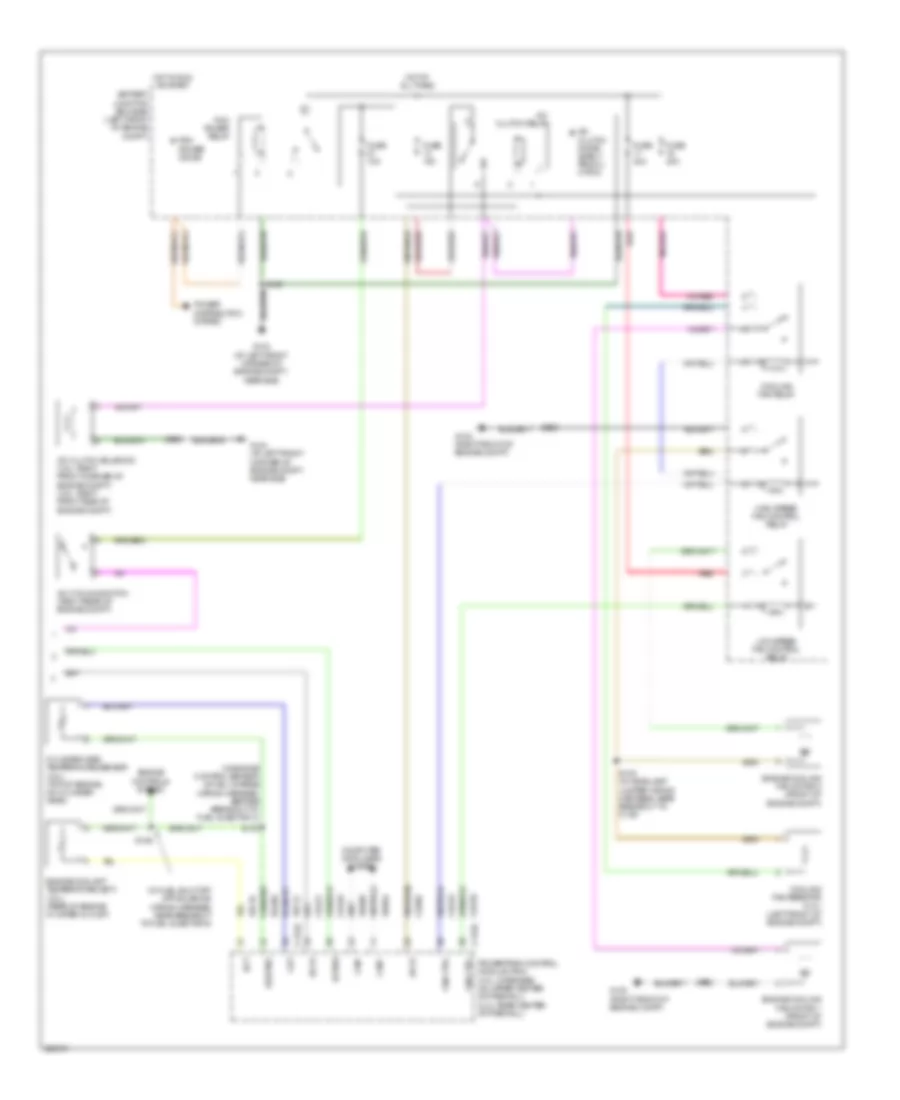
Automatic A/C Wiring Diagram, Hybrid (4 of 4) for Mercury Mariner Premier 2008
List of elements for Automatic A/C Wiring Diagram, Hybrid (4 of 4) for Mercury Mariner Premier 2008:
- (in dash panel to headlamp junction wiring harness, near breakout to battery junction box (bjb) s122
- (in dash panel to headlamp junction wiring harness, near breakout to battery junction box (bjb)) s120
- (near battery) g104
- A/c clutch diode
- A/c clutch relay
- A/c clutch solenoid (on air conditioner compressor)
- Battery junction box (bjb) (left rear of engine compt)
- Engine cooling fan dropping resistor 1 (left front of engine compt)
- Engine cooling fan motor 1 (left front of engine compt)
- Engine cooling fan motor 2 (right front of engine compt)
- Fan control
- Fan control relay 1
- Fan control relay 2
- Fuse 10a
- Fuse 15a
- Fuse 40a
- G102 (right front corner of engine compt)
- G104 (near battery)
- Hot at all times
- Hot in run or start
- Pcm power diode
- Pcm power relay
- Red
- Relay 3
- S114
- S115
- S118
- S125
- S126
- S134
- S140
Manual A/C Wiring Diagram, Except Hybrid (1 of 3) for Mercury Mariner Premier 2008
List of elements for Manual A/C Wiring Diagram, Except Hybrid (1 of 3) for Mercury Mariner Premier 2008:
- (in air conditioning jumper wiring harness, near breakout to front blower motor)
- Ambient temp sens
- Battery junction box (bjb) (left front of engine compt)
- Blwr sw h
- Blwr sw m-h
- Blwr sw m-l
- C2280a
- C2280b
- C2280e
- C2357a
- C2357b
- Cbp37
- Ch122
- Ch123
- Ch207
- Ch208
- Ch228
- Ch229
- Ch238
- Ch239
- Ch428
- Ch429
- Ch430
- Chs29
- Chs30
- Computer data lines system
- Defogger system
- Drv htd seat rly
- Drv temp dr ccw
- Drv temp dr cw
- Drv temp dr fdbk
- Evap temp sens
- Fr blower relay
- Front blower motor (right side of dash)
- Front blower motor relay
- Front blower motor resistor assembly (behind right side of dash)
- Fuse 10a
- Fuse 40a
- Fuse 5a
- G200 (behind right side of dash)
- G202 (behind left side of dash)
- Gd112
- Gd114
- Gnd
- Hot at all times
- Hot in run or acc
- Hot in run or start
- Hvac (emtc)
- Lh111
- Mode dr 1 ccw
- Mode dr 1 cw
- Mode dr 1 fdbk
- Ms can+
- Ms can-
- Pass htd seat rly
- Power distribution system
- Pwr gnd
- R-def
- Recirc dr ccw
- Recirc dr cw
- Recirculation blend door actuator (right side of dash, on hvac assembly)
- Rh111
- S201
- S202
- S224
- Sbp15
- Seats system
- Signal return
- Smart junction box (sjb) (below center of dash)
- Thermal limiter
- V batt
- V ign
- V ref 5v
- Vdb06
- Vdb07
- Vh406
- Vh407
- Vh436
- Vh440
Manual A/C Wiring Diagram, Except Hybrid (2 of 3) for Mercury Mariner Premier 2008
List of elements for Manual A/C Wiring Diagram, Except Hybrid (2 of 3) for Mercury Mariner Premier 2008:
- (behind center of dash) s210
- (in air conditioning jumper wiring harness, near c2029) s222
- (in air conditioning wiring harness, near recirculation blend door actuator) s223
- (right front of engine compt) g103
- Ambient air temperature sensor (behind left side of front grille)
- Driver temperature blend door actuator (right side of dash, on hvac assembly)
- Dual pressure switch (right front of engine compt)
- Evaporator discharge air temperature sensor (right side of dash, near evaporator)
- Mode door actuator (right side of dash, on hvac assembly)
Manual A/C Wiring Diagram, Except Hybrid (3 of 3) for Mercury Mariner Premier 2008
List of elements for Manual A/C Wiring Diagram, Except Hybrid (3 of 3) for Mercury Mariner Premier 2008:
- (in engine control sensor & fuel charge wiring harness, before breakout to fuel injector 3)
- (in fuel shut off off solenoid wiring harness, near breakout to fuel injector 6)
- A/c clutch diode (early produ- ction)
- A/c clutch relay
- A/c clutch solenoid (2.3l: right front corner of engine compt) (3.0l: right front side of engine compt)
- A/c cycling switch (right rear of engine compt)
- Accr
- Accs
- Acpsw
- Battery junction box (bjb) (left front of engine compt)
- C175b
- C175e
- Can+
- Can-
- Cec01
- Cec02
- Ch302
- Ch421
- Ch425
- Cht
- Computer data lines system
- Cooling fan relay
- Cooling fan resistor (2.3l) (left front of engine compt)
- Cylinder head temperature sensor (2.3l) (top of engine, on cylinder head)
- Ect
- Engine control system
- Engine coolant temperature (ect) (3.0l) (rear of engine in water outlet)
- Engine cooling fan motor 1 (front of engine compt)
- Engine cooling fan motor 2 (front of engine compt)
- Fan ctrl
- Fuse 10a
- Fuse 40a
- G102 (right front of engine compt)
- G104 (at left front corner of engine compt, near bjb)
- High speed fan control relay
- Hot at all times
- Hot in run or start
- Low speed fan control relay
- Pcm power diode
- Pcm power relay
- Power distribution system
- Powertrain control module (pcm) (3.0l: in recess on upper center of firewall) (2.3l: rear center of firewall)
- Re405
- Red
- S100
- S102
- S108 (in headlamp jumper wiring harness, near breakout to c139)
- S109
- S118
- S129
- Sigrtne
- Vdb04
- Vdb05
- Ve712
- Ve716