AIR CONDITIONING
Automatic A/C Wiring Diagram (1 of 2) for Oldsmobile Eighty-Eight LS 1999

List of elements for Automatic A/C Wiring Diagram (1 of 2) for Oldsmobile Eighty-Eight LS 1999:
- (body harness, 8 cm from right i/p cross-channel)
- (body harness, at right wheelhouse)
- (engine harness, 6 cm from a/c compressor clutch breakout)
- (i/p harness, behind center of dash)
- (top left side of dash)
- (top right side of dash)
- +5v
- A/c clutch relay (center rear of engine compartment)
- A/c compres- sor clutch
- A/c compres- sor clutch diode
- A/c fuse 30a
- A/c request
- Ambient temperature sensor (center front of vehicle)
- Battery
- Blower control
- Blower control module (on right side of engine, near blower motor)
- Blower feedback
- Blower motor
- Clock driver
- Computer data lines system
- Data line
- Data link connector (below left side of dash)
- E10
- E11
- E12
- E13
- E14
- E15
- E16
- Enable
- F10
- F11
- F12
- F13
- F14
- F15
- F16
- Fuse 10a
- Fuse 5a 15a
- Fuse 7e 20a
- Fuse 9c 10a
- G105 (right front of engine compartment)
- G201 (right kickpad)
- Ground
- Heater and a/c programmer (behind right side of dash)
- Hot at all times
- Hot in run
- Hot in run or start
- I/p fuse block
- Ign
- Ignition
- Inside air temperature sensor (behind left side of dash)
- Left sunload sensor
- Motor ctrl
- Nca
- Pass ctrl status
- Passenger air mix valve actuator
- Pnk
- Red
- Rh i/p junction block
- Right maxi fuse block
- Right sunload sensor
- S102 (body harness, near a/c accumulator)
- S108
- S207 (body harness, 12 cm from center i/p cross-channel)
- S241 (body harness, 40 cm from lamp control module)
- S268 (body harness, 26 cm from heater and a/c programmer)
- S270
- S277
- S279 (body harness, 2 cm from end of right i/p cross- channel)
- S308 (body harn, near g203)
- Sense
- Sensor ground
- Sensor input
- Sensor return
- Signal driver
- Solar sensor input
- Tan
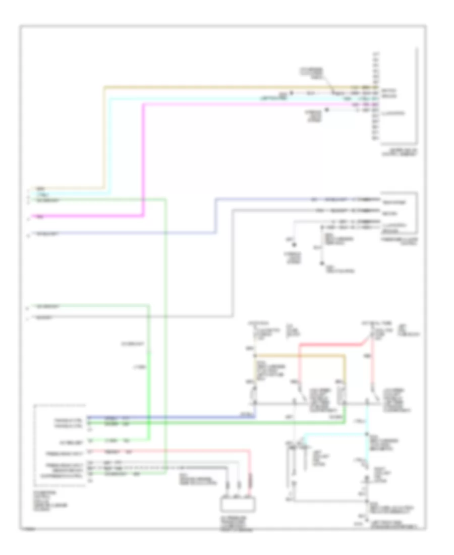
Automatic A/C Wiring Diagram (2 of 2) for Oldsmobile Eighty-Eight LS 1999
List of elements for Automatic A/C Wiring Diagram (2 of 2) for Oldsmobile Eighty-Eight LS 1999:
- (i/p harness, 12.5 cm from radio)
- (left front side of engine compartment)
- A/c pressure transducer (lower right front of engine)
- A/c request
- Clg fan/tcc fuse 5c 10a
- Compressor control
- Cool fns fuse 40a
- Fan relay ctrl
- G104
- G201 (right kickpad)
- G202 (left kick pad)
- Ground
- Heater and a/c control assembly
- High speed coolant fan relay (left rear of engine compartment)
- Hot at all times
- Hot in run
- I/p fuse block
- Ignition
- Illumination
- Interior lights system
- Left coolant fan motor
- Left maxi fuse block
- Low speed coolant fan relay (left rear of engine compartment)
- Nca
- Passenger climate control
- Powertrain control module (near air cleaner housing)
- Pressure sw input
- Red
- Return
- Right coolant fan motor
- S104 (body harness, 27 cm from left maxi fuse box)
- S121 (engine harness, near accumulator)
- S124 (body harness, 10 cm from ebcm/ebtcm)
- S128 (body harn, 6.5 cm from fan motor breakout)
- S213
- S308 (body harness, near g203)
- Sensor return
- Temp offset
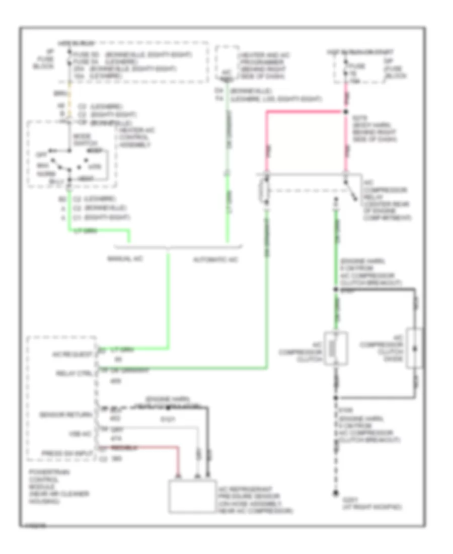
Compressor Wiring Diagram for Oldsmobile Eighty-Eight LS 1999
List of elements for Compressor Wiring Diagram for Oldsmobile Eighty-Eight LS 1999:
- (bonneville)
- (bonneville, eighty-eight) (lesabre)
- (eighty-eight)
- (engine harn, 6 cm from a/c compressor clutch breakout)
- (engine harn, near accumulator)
- (lesabre)
- A/c compressor clutch
- A/c compressor clutch diode
- A/c compressor relay (center rear of engine compartment)
- A/c refrigerant pressure sensor (on hose assembly, near a/c compressor)
- A/c req
- A/c request
- Automatic a/c
- B h
- Bi-lv
- C2 c2
- D4 (bonneville)
- Def
- F4 (lesabre, lss, eighty-eight)
- Fuse 5d fuse 5a 25a 15a
- Fuse 7e 10a
- G201 (at right kickpad)
- Heater and a/c programmer (behind right side of dash)
- Heater-a/c control assembly
- Hot in run
- Hot in run or start
- Htr
- I/p fuse block
- Manual a/c
- Max
- Mode switch
- Nca
- Norm
- Off
- Pnk
- Powertrain control module (near air cleaner housing)
- Press sw input
- Relay ctrl
- S106
- S107
- S121
- S279 (body harn, behind right side of dash)
- Sensor return
- Vent
- Vsb a/c
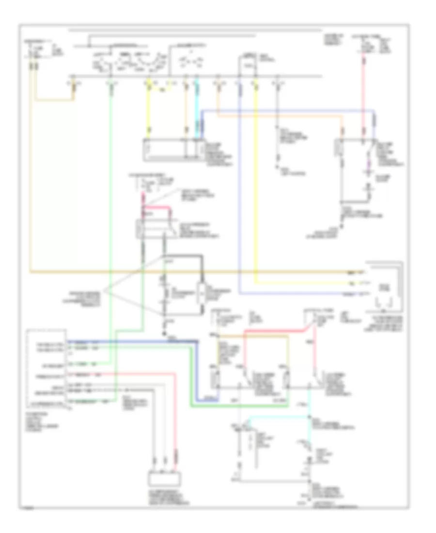
Manual A/C Wiring Diagram for Oldsmobile Eighty-Eight LS 1999
List of elements for Manual A/C Wiring Diagram for Oldsmobile Eighty-Eight LS 1999:
- (body harness, behind right side of dash)
- (engine harness, 6 cm from a/c compressor clutch breakout)
- (left front of engine compartment)
- A/c compressor clutch
- A/c compressor clutch diode
- A/c compressor relay (center rear of engine compartment)
- A/c fuse 30a
- A/c refrigerant pressure sensor (on hose assembly, near a/c compressor)
- A/c request
- A/c temperature valve actuator (behind center of dash, top of plenum)
- Bi-lv
- Blower motor
- Blower motor resistor (center rear of engine compartment)
- Blower relay (center rear of engine compartment)
- Blower switch
- C tan
- Clg fan/tcc fuse 5c 10a
- Compressor ctrl
- Cool
- Cool fns fuse 40a
- Def
- Fan relay ctrl
- Fuse 5d 25a
- Fuse 7e 10a
- G104
- G105 (right front of engine compt)
- G202 (left kickpad)
- G203 (at right kickpad)
- Heater-a/c control assembly
- High speed coolant fan relay (left rear of engine compartment)
- Hot at all times
- Hot in run
- Hot in run or start
- Htr
- I/p fuse block
- Left coolant fan motor
- Left maxi fuse block
- Low speed coolant fan relay (left rear of engine compartment)
- Max
- Mode switch
- Nca
- Norm
- Off
- Pnk
- Pnk s279
- Powertrain control module (near air cleaner housing)
- Press sw input
- Red
- Right coolant fan motor
- Right maxi fuse block
- S104 (body harn, 27 cm from left maxi fuse block)
- S107
- S121 (engine harn, near accumu- lator)
- S124 (body harness, 10 cm from ebcm/ebtcm)
- S128 (body harness, 6.5 cm from fan motor breakout)
- S213 (i/p harness, behind center of dash)
- Sensor return
- Solid state
- Tan
- Temp control
- Vent
- Vsb a/c
- Warm