ANTI-LOCK BRAKES
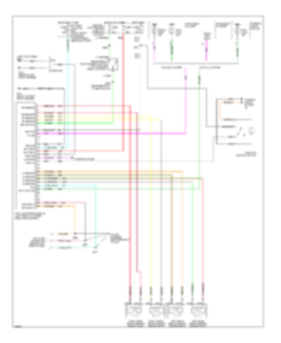
Anti-lock Brake Wiring Diagrams for Ford Crown Victoria 2001
List of elements for Anti-lock Brake Wiring Diagrams for Ford Crown Victoria 2001:
- (in main harness, near breakout to dlc)
- (left kick panel) g200
- Analog cluster
- Anti- lock ind
- Anti-lock brake module (left front of upper radiator support)
- Anti-lock ind
- Battery
- Battery junction box (right front of engine compartment, behind battery)
- Bpp switch
- Brake pedal position (bpp) switch (top of brake pedal support)
- Central junction box (left of steering column)
- Data link connector (behind left side of dash)
- Digital cluster
- Dlc
- Fuse 10a
- Fuse 15a
- Fuse 50a
- G101 (front of right front fender)
- G104 (rear of left front fender)
- Gasoline
- Ground
- Hot at all times
- Hot in run
- Ign
- Ignition
- Instrument cluster
- Interior lights system jr
- Left front brake sensor (brake ass'y)
- Left rear brake sensor (brake ass'y)
- Lf sensor
- Lr sensor
- Nca
- Ngv
- Red
- Red/pnk
- Rf sensor
- Right front brake sensor (brake ass'y)
- Right rear brake sensor (brake ass'y)
- Rr sensor
- S112
- S231
- S258 (near breakout to bpp switch)
- S265
- S271
- S296
- S297
- Scp bus (+)
- Scp bus (-)
- Tc ind
- Tcsw in
- Tract asst ind
- Tract asst input
- Traction control switch
- Warning
- Warning lamps module
- Warning system
 English