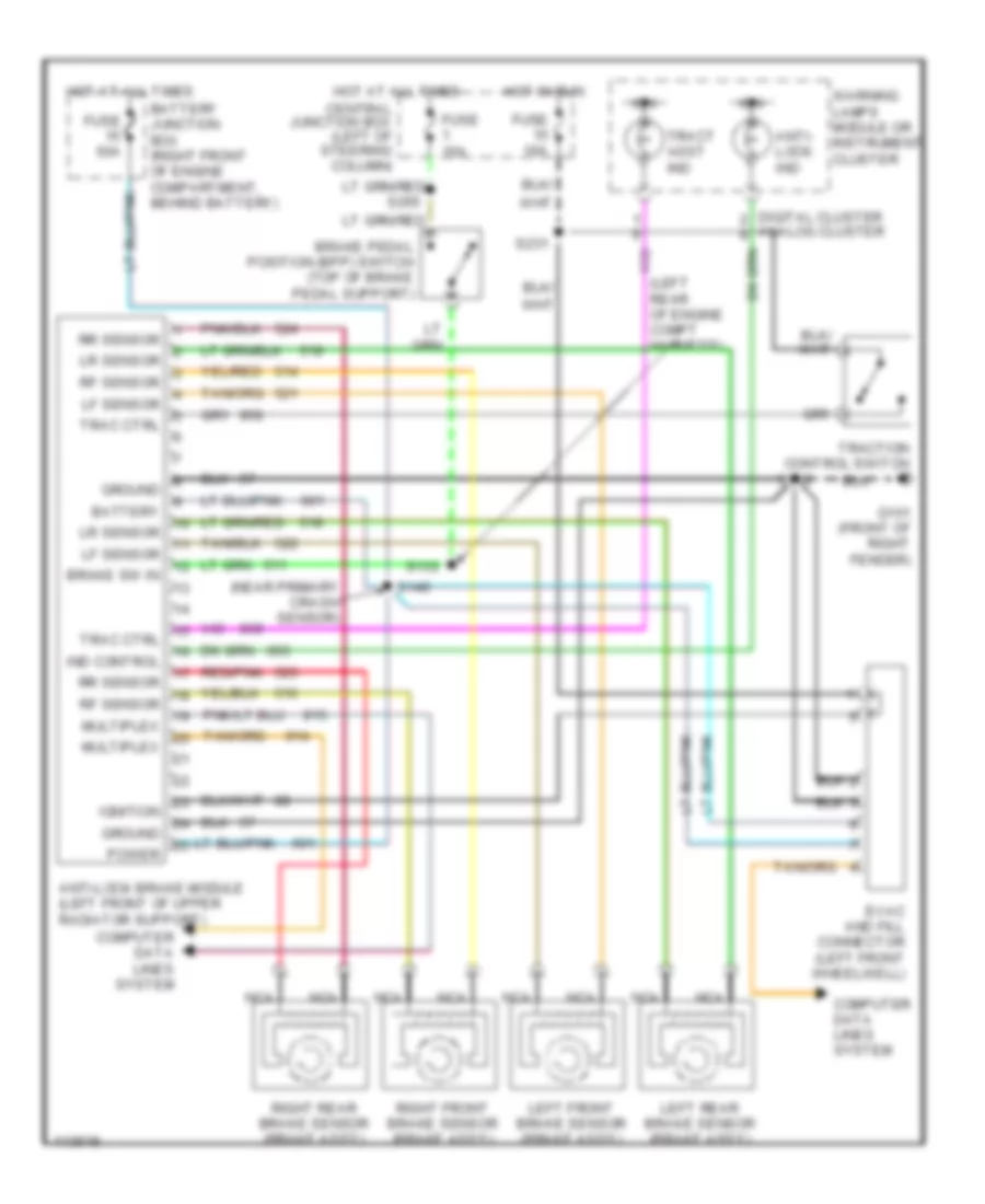
ANTI-LOCK BRAKES
Anti-lock Brake Wiring Diagrams for Ford Crown Victoria S 1999
List of elements for Anti-lock Brake Wiring Diagrams for Ford Crown Victoria S 1999:
- (left rear of engine compt harness)
- (near primary crash sensor)
- Anti- lock ind
- Anti-lock brake module (left front of upper radiator support)
- Battery
- Battery junction box (right front of engine compartment, behind battery)
- Brake pedal position (bpp) switch (top of brake pedal support)
- Brake sw in
- Central junction box (left of steering column)
- Computer data lines system
- Digital cluster analog cluster
- Evac and fill connector (left front wheelwell)
- Fuse 10a
- Fuse 15a
- Fuse 50a
- G101 (front of right fender)
- Ground
- Hot at all times
- Hot in run
- Ign
- Ignition
- Ind control
- Left front brake sensor (brake ass'y)
- Left rear brake sensor (brake ass'y)
- Lf sensor
- Lr sensor
- Multiplex
- Nca
- Power
- Red/pnk
- Rf sensor
- Right front brake sensor (brake ass'y)
- Right rear brake sensor (brake ass'y)
- Rr sensor
- S112
- S132
- S146
- S231
- Trac ctrl
- Tract asst ind
- Traction control switch
- Warning lamps module or instrument cluster
 English