ANTI-LOCK BRAKES
Anti-lock Brake Wiring Diagrams for Ford Escape 2002
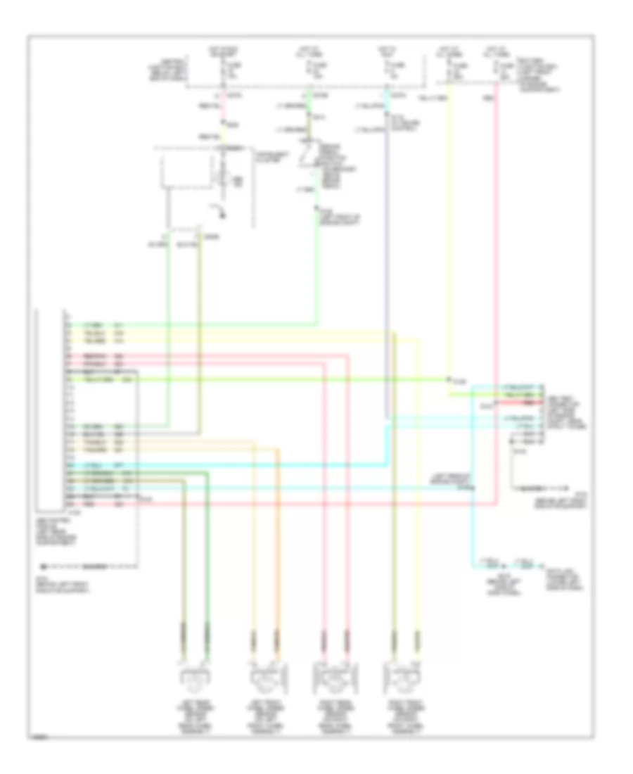
List of elements for Anti-lock Brake Wiring Diagrams for Ford Escape 2002:
- (left rear of engine compt) s125
- Abs control module (left rear side of engine compartment)
- Abs ind
- Abs test connector (left side
- Battery junction box (left front corner of engine compartment)
- Brake pedal position switch (on bracket above brake pedal)
- C135
- C220b
- C220c
- C270a
- C270c
- C270e
- Central junction box (below left end of dash)
- Data link connector (lower left side of dash)
- Fuse 10a
- Fuse 15a
- Fuse 25a
- Fuse 5a
- Fuse 60a
- G104 (behind left front radiator support)
- Hot at all times
- Hot in run
- Hot in run or start
- Instrument cluster
- Left front wheel speed sensor (on left front wheel assembly)
- Left rear wheel speed sensor (on left rear wheel assembly)
- Of engine compt, near strut tower)
- Red
- Red/pnk
- Right front wheel speed sensor (on right front wheel assembly)
- Right rear wheel speed sensor (on right rear wheel assembly)
- S119 (w/ cruise control)
- S123
- S124
- S126
- S132
- S139 (left front of engine compt)
- S219 (behind left side of dash panel)
- S222
- S314
 English