ANTI-LOCK BRAKES
All-Wheel ABS Wiring Diagram for Ford F450 Super Duty 2000

List of elements for All-Wheel ABS Wiring Diagram for Ford F450 Super Duty 2000:
- (in left side of engine compt) abs test connector
- (not used)
- 15-cf6a
- 30-cf13a
- 30-cf6a
- 31-cf6
- 4-ec9a
- 5-ec9a
- 8-cf32
- 8-cf34
- 8-cf38
- 8-cf40
- 9-cf32
- 9-cf34
- 9-cf38
- 9-cf40
- Abs control module (in left rear corner of engine compartment, under master cylinder)
- Battery junction box (bjb) (in left rear corner of engine compt)
- Brake fluid level switch (on top of master cylinder reservoir)
- Brake pedal position (on brake pedal support bracket)
- C270d
- C270f
- Can +
- Can -
- Central junction box (cjb) (behind left side of dash)
- Clutch pedal position switch (m/t) (on clutch pedal support)
- Computer data lines system
- Fuse 15a
- Fuse 20a
- Fuse 30a
- Fuse 7.5a
- G101 (at left front of engine compartment)
- G103 (at left side of engine compartment)
- Gnd
- Hot at all times
- Hot in start or run
- Instrument cluster
- Left front wheel speed sensor (on left front wheel hub)
- Left rear wheel speed sensor (on left rear wheel hub)
- Low brake fluid level/ park brake indicator
- Micro- processor
- Nca
- Red
- Right front wheel speed sensor (on right front wheel hub)
- Right rear wheel speed sensor (on right rear wheel hub)
- S118
- S202 (in main wiring harness, near breakout for stoplamp switch)
- Speed control servo (left side of engine compartment)
- Stoplamp switch (on brake pedal support bracket)
- Vbatt
- Vpwr
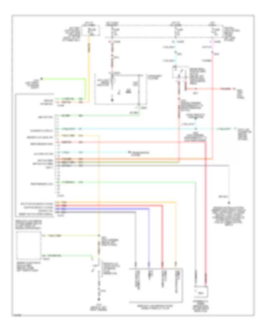
Rear Wheel ABS Wiring Diagram for Ford F450 Super Duty 2000
List of elements for Rear Wheel ABS Wiring Diagram for Ford F450 Super Duty 2000:
- 22k ohm
- 4x4 high/low ind
- 5.6k ohm
- Abs ind ctrl
- Anti-lock brake indicator
- Battery junction box (in left side of engine compt, on top of wheelwell)
- Bpp switch feed
- Brake fluid level sw
- Brake fluid level switch (on brake fluid reservoir)
- Brake pedal position (bpp) switch (behind left side of dash, above brake pedal)
- C104a
- C104b
- C240a
- C242b
- C250a
- C250c
- Central junction box (behind lower left side of dash)
- Common (12 v)
- Common (12v)
- Computer data lines system
- Data link connector (behind center of dash)
- Diagnostic circuit
- Differential speed sensor (dss) (on center of rear axle)
- Dump solenoid (1-2 ohms)
- Engine controls system (generic electronic module (gem), instrument cluster, central junction box, overhead console module, powertrain control module, speed control servo)
- Fuse 10a
- Fuse 5a
- Fuse 60a
- G100 (left front of engine compt)
- G104 (rear of left front fender)
- G200 (left kick panel)
- Generic electronic module (gem) (behind lower left side of dash)
- Ground
- Hot at all times
- Hot in run
- Hot in run or start
- Ignition feed
- Instrument cluster
- Isolation solenoid (4 ohms)
- Power (b+)
- Rear anti-lock brake system (rabs) hydraulic valve
- Rear anti-lock brake system (rabs) module (in left front of engine compartment)
- Rear sensor (high)
- Rear sensor (low)
- Red
- Red/pnk
- Reset switch (normally open)
- Reset switch (open normal)
- S102
- S108 (engine harness, near breakout to brake pressure switch)
- S201
- S201 (main harness, behind left side of dash)
- S213
- S221
- S225 (main harness, (near breakout to customer access)
- S235
- Tan
- Tan/red
- Transmissions system
- Vss (+)