ANTI-LOCK BRAKES
Anti-lock Brakes Wiring Diagram (1 of 2) for Ford Flex Limited 2009

List of elements for Anti-lock Brakes Wiring Diagram (1 of 2) for Ford Flex Limited 2009:
- Anti lock brake system (abs) module (left rear of engine compt)
- Battery junction box (bjb) (left side of engine compt)
- Brake pedal position (bpp) switch (left side of dash)
- Cbp34
- Computer data lines system
- Fuse 10a
- Fuse 20a
- Fuse 40a
- G101 (left front of engine compt)
- Gd120
- Headlamp junction near breakout to right front of engine compt)
- Hot at all times
- Hs can +
- Hs can -
- Hs can yaw +
- Hs can yaw -
- Ivd rtn
- Left front wheel speed sensor (left front wheel hub assembly)
- Left rear wheel speed sensor (left rear wheel hub assembly)
- Lf sens high
- Lf sens low
- Logic gnd
- Lr sens high
- Lr sens low
- Motor gnd
- Mtr b+
- Nca
- Pcm power relay
- Rca09
- Rca17
- Rca18
- Rca19
- Rca20
- Red
- Rf sens high
- Rf sens low
- Right front wheel speed sensor (right front wheel hub assembly)
- Right rear wheel speed sensor (right rear wheel hub assembly)
- Rr sens high
- Rr sens low
- Run
- S190 (to headlamp junction near breakout to left rear of engine compt)
- S192
- S196
- Sas a
- Sas b
- Sbb09
- Sbb12
- Speed control deactivation switch (under left side of dash)
- Valve b+
- Vca03
- Vca04
- Vca05
- Vca06
- Vca23
- Vca24
- Vcs06
- Vcs07
- Vdb04
- Vdb05
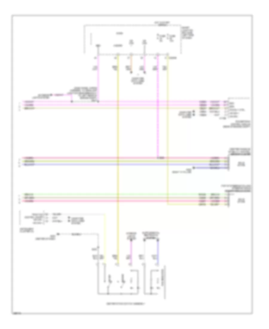
Anti-lock Brakes Wiring Diagram (2 of 2) for Ford Flex Limited 2009
List of elements for Anti-lock Brakes Wiring Diagram (2 of 2) for Ford Flex Limited 2009:
- (center console) stability control sensor cluster
- (dash panel wiring harness, to headlamp junction near breakout to left rear of engine compt) s213
- (top of steering column) steering angle sensor module (sasm)
- Boo
- Bps
- C175b
- C2280b
- Cbp35
- Ccb08
- Ce237
- Center stack switch assembly
- Ces09
- Computer data lines system
- Exterior lights system
- Fuse 10a
- Fuse 5a
- G202 (center of dash)
- G305 (right "c" pillar)
- Hazard
- Hot in start or run
- Hs can +
- Hs can -
- Instrument cluster (ic)
- Interior lights system
- Ivd sw
- Micro
- Ms can +
- Ms can -
- Pad indicator
- Pcm rly ctrl
- Powertrain control module (rear of engine compt)
- Rca09
- S222
- S223
- Smart junction box (sjb) (left side of dash)
- Solid state
- Traction control on/off hs can -
- Vcs06
- Vcs07
- Vdb04
- Vdb05