ANTI-LOCK BRAKES
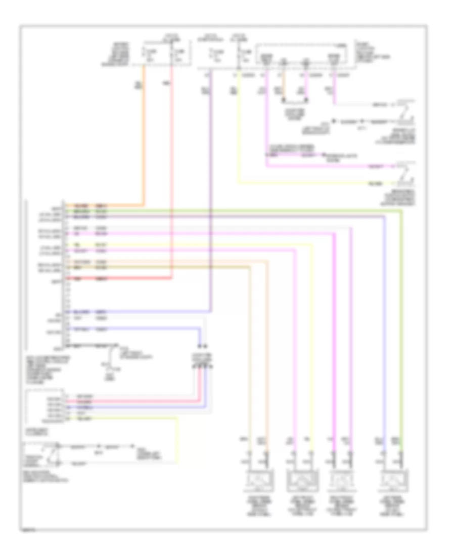
Anti-lock Brakes Wiring Diagram for Ford Focus SES 2008
List of elements for Anti-lock Brakes Wiring Diagram for Ford Focus SES 2008:
- (in main wiring harness, near breakout to g203) s223
- (not used)
- Anti-lock brake system (abs) control module (left rear corner of engine compartment, under master cylinder)
- Battery junction box (bjb) (left rear corner of engine compt)
- Brake fluid level switch (on top of master cylinder reservoir)
- Brake fluid sw
- Brake pedal position switch (on brake pedal support bracket)
- Brake pedal sw
- C126
- C2280b
- C2280d
- C2280f
- Cbp31
- Computer data lines system
- Exterior lights system
- Fuse 10a
- Fuse 15a
- Fuse 20a
- Fuse 40a
- G101 (left front of engine compt)
- G102 (left front of engine compt)
- G203 (under left side of dash)
- Gd122
- Gnd
- Hot at all times
- Hot in start or run
- Hs can+
- Hs can-
- Ign
- Instrument cluster (ic)
- Left front wheel speed sensor (on left front wheel hub)
- Left rear wheel speed sensor (at left rear wheel)
- Lf whl spd+
- Lf whl spd-
- Logic
- Lr whl spd+
- Lr whl spd-
- Ms can+
- Ms can-
- Nca
- Pad indicator/ traction control/ ambient lighting switch
- Rca17
- Rca18
- Rca19
- Rca20
- Red
- Rf whl spd+
- Rf whl spd-
- Right front wheel speed sensor (on right front wheel hub)
- Right rear wheel speed sensor (at right rear wheel)
- Rr whl spd+
- Rr whl spd-
- S111
- S215
- Sbb09
- Sbb18
- Smart junction box (sjb) (behind left side of dash)
- Tcs on/off
- Traction on/off switch
- Vbatt
- Vca03
- Vca04
- Vca05
- Vca06
- Vdb04
- Vdb05
 English