ANTI-LOCK BRAKES
Anti-lock Brake Wiring Diagrams for Ford Mustang GT 2002
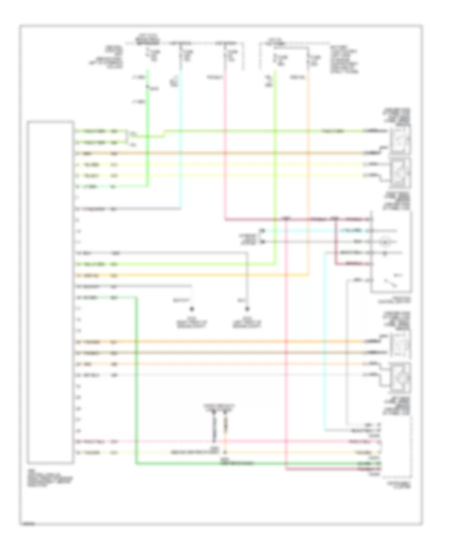
List of elements for Anti-lock Brake Wiring Diagrams for Ford Mustang GT 2002:
- (inboard side of wheel hub) left front wheel speed sensor
- (inboard side of wheel hub) right rear wheel speed sensor
- 3.8l
- 4.6l
- Abs control module (right front of engine compartment, behind radiator)
- Battery junction box (left side of engine compartment, forward of strut tower)
- C220a
- C220b
- Central junction box (behind dash, left of steering column)
- Computer data lines system
- Fuse 15a
- Fuse 20a
- Fuse 50a
- G102 (left front of engine compt)
- G103 (right front of engine compt)
- Hot at all times
- Hot in run
- Hot with brake pedal depressed
- Instrument cluster
- Interior lights system
- Left rear wheel speed sensor (inboard side of wheel hub)
- Nca
- Right front wheel speed sensor (inboard side of wheel hub)
- S252 (behind center of dash)
- S253 (center of dash)
- S257
- S275
- S284
- Traction control switch
 English