ANTI-LOCK BRAKES
Anti-lock Brakes Wiring Diagram for Ford Mustang GT 2006
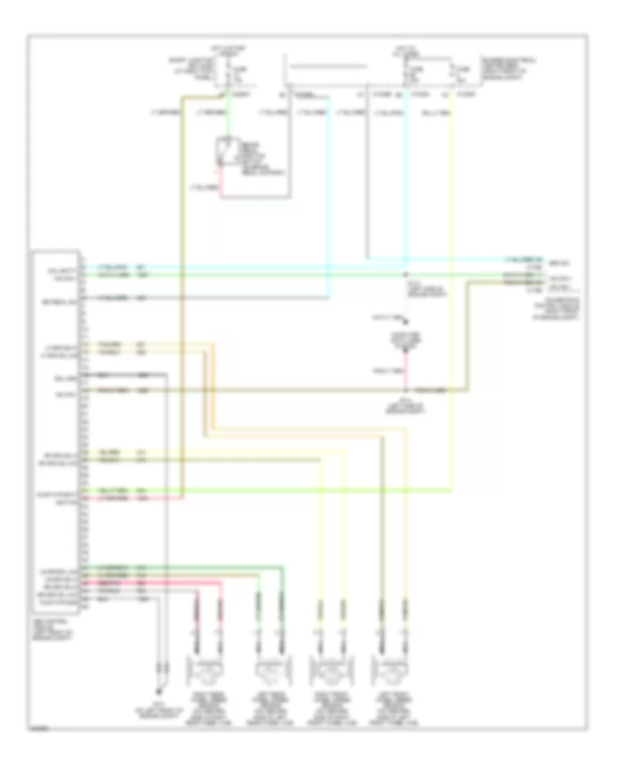
List of elements for Anti-lock Brakes Wiring Diagram for Ford Mustang GT 2006:
- Abs control module (left front of engine compt)
- Br pedal sw
- Brake pedal position switch (on brake pedal support)
- Brk sw
- Bussed electrical center (bec) (right front of engine compt)
- C1035a
- C1035b
- C1035d
- C175b
- C175e
- C2280h
- Coil batt+
- Computer data lines system
- Ecu gnd
- Fuse 10a
- Fuse 30a
- Fuse 40a
- G101 (on left front of engine compt)
- Hot at all times
- Hot in start or run
- Hs can +
- Hs can -
- Ignition
- Left front wheel speed sensor (on inboard side of left front wheel hub)
- Left rear wheel speed sensor (on inboard side of left rear wheel hub)
- Lf spd sn hi
- Lf spd sn low
- Lr spd sn hi
- Lr spd sn low
- Nca
- Powertrain control module (right front of engine compt)
- Pump mtr batt
- Pump mtr gnd
- Red/pnk
- Rf spd sn hi
- Rf spd sn low
- Right front wheel speed sensor (on inboard side of right front wheel hub)
- Right rear wheel speed sensor (on inboard side of right rear wheel hub)
- Rr spd sn hi
- Rr spd sn low
- S113 (left side of engine compt)
- S114 (left side of engine compt)
- Smart junction box (sjb) (at right kick panel)
 English