ANTI-LOCK BRAKES
Anti-lock Brakes Wiring Diagram for Ford Mustang GT 2010
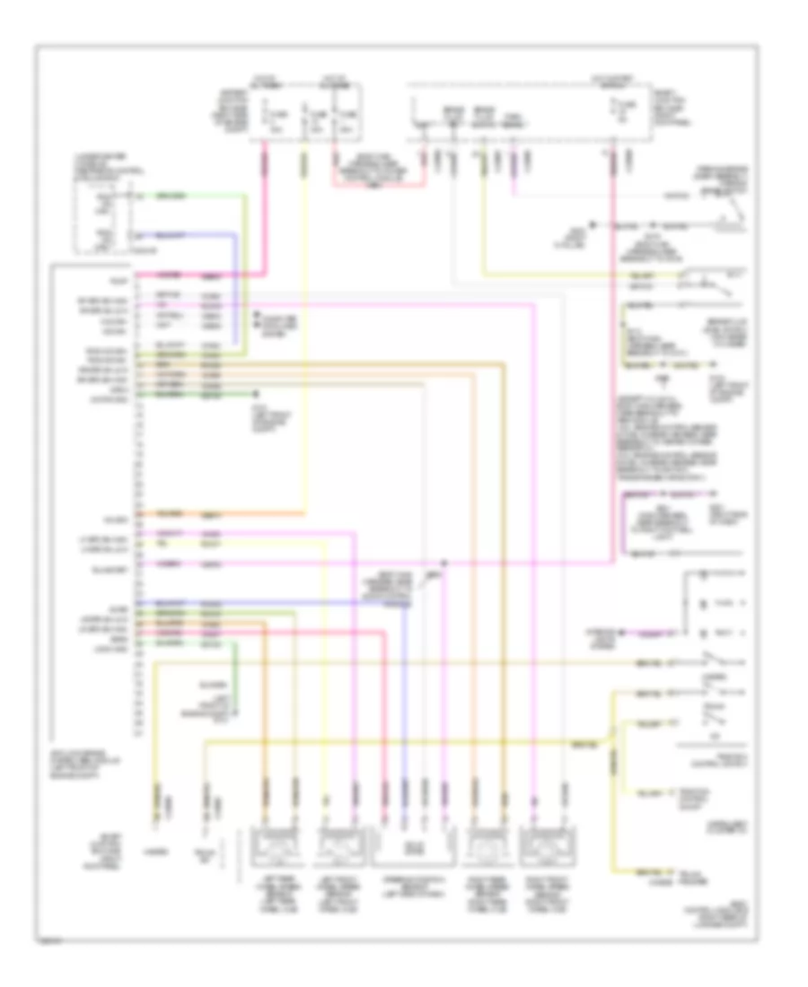
List of elements for Anti-lock Brakes Wiring Diagram for Ford Mustang GT 2010:
- (body main harness, near breakout to audio control module)
- (body main harness, near breakout to power control module) s114
- (except 4.0l & 5.4l: body main harness, near breakout to abs module) (4.0l: engine control sensor & fuel charge harness, near breakout to heated oxygen sensor 21) (5.4l: engine control sensor & fuel charge harness, near breakout to ignition transformer capacitor 1)
- (left front of engine compt)
- (parking brake lever assembly) parking brake switch
- (under center console) restraints control module (rcm)
- Anti-lock brake system (abs) module (left front of engine compt)
- Batt
- Battery junction box (bjb) (right side of engine compt)
- Body control module b (right rear of luggage compt)
- Brake fluid level switch (on master cylinder)
- Brake fluid sw
- Brake fluid sw rtn
- C2041b
- C2280b
- C2280c
- C2280f
- C2280g
- Cbp34
- Computer data lines system
- Control on/off
- Fuse 30a
- Fuse 40a
- Fuse 5a
- Fuse 80a
- G101
- G101 (left front of engine compt)
- G104 (left front of engine compt)
- G201 (right side of dash)
- G203 (right "a" pillar)
- Gd120
- Hazard
- Hot at all times
- Hot in start or run
- Hs can+
- Hs can-
- Instrument cluster (ic)
- Interior lights system
- Ivd
- Left front wheel speed sensor (left front wheel hub)
- Left rear wheel speed sensor (left rear wheel hub)
- Lf spd sn high
- Lf spd sn low
- Logic gnd
- Lr spd sn high
- Lr spd sn low
- Motor gnd
- Park brake
- Pump
- Rca17
- Rca18
- Rca19
- Rca20
- Rcs hs can+
- Rcs hs can-
- Rcs02
- Red
- Rf spd sn high
- Rf spd sn low
- Right front wheel speed sensor (right front wheel hub)
- Right rear wheel speed sensor (right rear wheel hub)
- Rr spd sn high
- Rr spd sn low
- Run/start
- S100
- S113 (body main harness, near breakout to g101)
- S201 (main harness, near breakout to right footwell light)
- S235
- S319 (body main harness, near breakout to c919)
- Sas a
- Sas b
- Sbb08
- Sbb10
- Smart junction box (sjb) (right kick panel)
- Solid state
- Steering position sensor (left side of dash)
- Swar
- Traction
- Traction control switch
- Trunk
- Trunk release c4368b
- Trunk sw
- Valve s
- Vca03
- Vca04
- Vca05
- Vca06
- Vca23
- Vca24
- Vcs06
- Vcs07
- Vdb04
- Vdb05
 English