ANTI-LOCK BRAKES
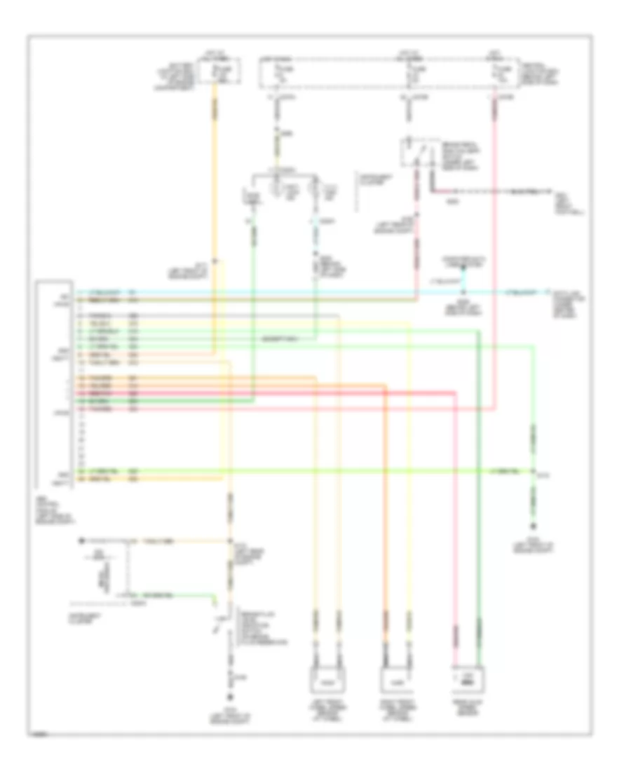
Anti-lock Brake Wiring Diagrams for Ford Pickup F150 2002
List of elements for Anti-lock Brake Wiring Diagrams for Ford Pickup F150 2002:
- (except ngv)
- 4 x 4 high ind
- Abs control module (left side of engine compt)
- Anti- lock ind
- Battery junction box (in left side of engine compartment)
- Bias ckt
- Brake fluid level indicator switch (on brake fluid reservoir)
- Brake pedal position (bpp) switch (under left side of dash)
- C220a
- C270a
- C270b
- Central junction box (behind left side of dash)
- Computer data lines system
- Data link connector (under center of dash)
- Fuse 10a
- Fuse 50a
- Fuse 5a
- G104 (left front of engine compt)
- G201 (left front footwell)
- Gnd
- Hot at all times
- Hot in run
- Instrument cluster
- Iso
- Left front wheel speed sensor (at wheel)
- Nca
- Ohm
- Processor micro-
- Rear axle speed sensor
- Red/pnk
- Right front wheel speed sensor (at wheel)
- S106
- S160 (left rear of engine compt)
- S170 (left rear of engine compt)
- S171 (left front of engine compt)
- S172
- S208
- S229 (behind left side of dash)
- S232 (behind left side of dash)
- S265
- Tan/red
- Vbatt
- Vpwr
 English