ANTI-LOCK BRAKES
Anti-lock Brake Wiring Diagrams, with Traction Control for Ford Taurus SES 2002

List of elements for Anti-lock Brake Wiring Diagrams, with Traction Control for Ford Taurus SES 2002:
- Abs control module (left front of engine compt, below battery)
- Abs ind control
- Abs indicator
- Abs pump motor
- Battery junction box (front center of engine compt, behind radiator)
- Bpp switch
- Brake fluid level
- Brake fluid level switch (left rear of engine compt, to right of master cylinder)
- Brake pedal position (bpp) switch (under dash, upper front side of brake pedal)
- C201a
- C220a
- C220b
- Central junction box (under left side of dash)
- Compt)
- Computer data lines system
- Data link
- Data link connector (mounted on dash, below steering column)
- Front
- Fuse 10a
- Fuse 15a
- Fuse 20a
- Fuse 40a
- G104 (front of right front fender)
- G107 (left front fender)
- G108 (left front fender)
- G201 (behind center of dash)
- Generic electronic module (gem) (under left side of dash)
- Ground
- Hot at all times
- Hot in run
- Hot in run or start
- Ignition
- Illum- ination
- Indicator tcs
- Instrument cluster
- Interior lights system
- Left dump valves
- Left front wheel speed sensor (in left front wheelwell, mounted on brake assembly)
- Left iso valves
- Left rear wheel speed sensor (in left rear wheelwell, mounted on brake assembly)
- Lf wheel sensor
- Lr wheel sensor
- Nca
- On/ off
- Rear
- Red/pnk
- Relay box
- Rf wheel sensor
- Right dump valves
- Right front wheel speed sensor (in right front wheelwell, mounted on brake assembly)
- Right iso valves
- Right rear wheel speed sensor (in right rear wheelwell, mounted on brake assembly)
- Rr wheel sensor
- S137
- S207
- S209
- S212
- S213 (under left side of dash)
- S217 (behind dash, near hvac unit)
- S218 (behind dash, near hvac unit)
- Solid state
- Tan/red
- Traction control off
- Traction control sw
- Traction control switch
- Traction ind control
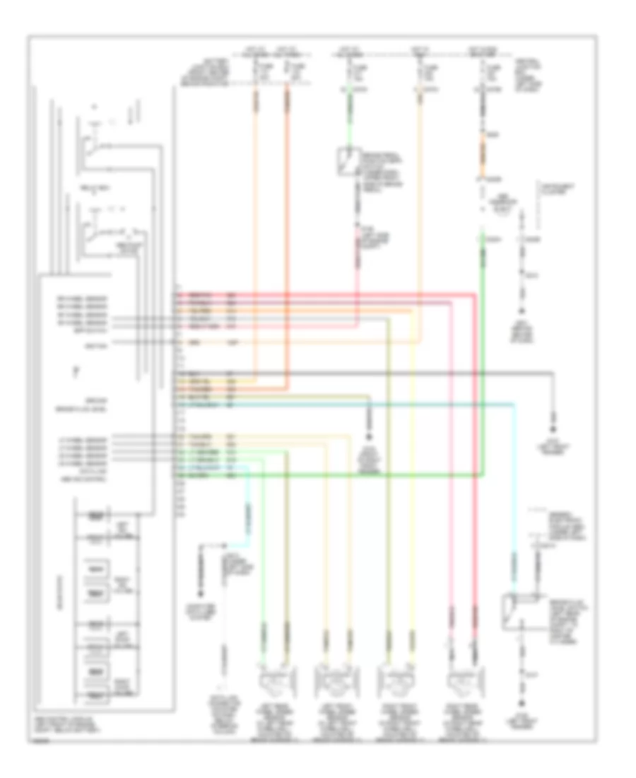
Anti-lock Brake Wiring Diagrams, without Traction Control for Ford Taurus SES 2002
List of elements for Anti-lock Brake Wiring Diagrams, without Traction Control for Ford Taurus SES 2002:
- Abs control module (left front of engine compt, below battery)
- Abs ind control
- Abs indicator
- Abs pump motor
- Battery junction box (front center of engine compt, behind radiator)
- Bpp switch
- Brake fluid level
- Brake fluid level switch (left rear of engine compt, to right of master cylinder)
- Brake pedal position (bpp) switch (under dash, upper front side of brake pedal)
- C201a
- C220a
- C220b
- Central junction box (under left side of dash)
- Compt)
- Computer data lines system
- Data link
- Data link connector (mounted on dash, below steering column)
- Front
- Fuse 10a
- Fuse 15a
- Fuse 20a
- Fuse 40a
- G104 (front of right front fender)
- G107 (left front fender)
- G108 (left front fender)
- G201 (behind center of dash)
- Generic electronic module (gem) (under left side of dash)
- Ground
- Hot at all times
- Hot in run
- Hot in run or start
- Ignition
- Instrument cluster
- Left dump valves
- Left front wheel speed sensor (in left front wheelwell, mounted on brake assembly)
- Left iso valves
- Left rear wheel speed sensor (in left rear wheelwell, mounted on brake assembly)
- Lf wheel sensor
- Lr wheel sensor
- Nca
- Rear
- Red/pnk
- Relay box
- Rf wheel sensor
- Right dump valves
- Right front wheel speed sensor (in right front wheelwell, mounted on brake assembly)
- Right iso valves
- Right rear wheel speed sensor (in right rear wheelwell, mounted on brake assembly)
- Rr wheel sensor
- S137
- S209
- S212
- S213 (under left side of dash)
- Solid state
- Tan/red