ANTI-LOCK BRAKES
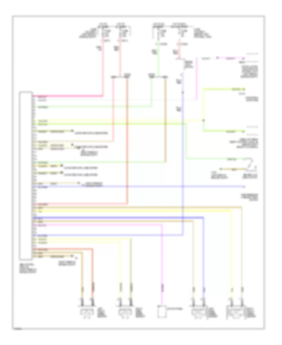
Anti-lock Brakes Wiring Diagram, with Dynamic Stability Control for MINI Cooper 2003

List of elements for Anti-lock Brakes Wiring Diagram, with Dynamic Stability Control for MINI Cooper 2003:
- (left door) (coupe) (under left rear seat) (convertible)
- (lower steering column) steering angle sensor
- (right rear of engine compt)
- Abs/dsc unit (right rear of
- Brake fluid level switch (left side of engine compt)
- Brake light switch
- Computer data lines system
- Digital motor electronics control unit (left side of engine compt)
- Dsc motion sensor (under lever cover)
- Engine compt)
- Fuse f06 30a
- Fuse f2 5a
- Fuse f33 10a
- Fuse f40 5a
- Fuse f6 5a
- Fuse fl6 40a
- Fuse holder 2 (behind left footwell trim)
- Fuse holder 3 (left side of engine compt)
- Headlight beam height control module (behind right side of glove box)
- Headlights system
- Hot at all times
- Hot in accy, run and start
- Hot in on or start
- Hydraulic brake pressure sensor
- Left front speed sensor
- Left rear speed sensor
- Navigation computer
- Nca
- Right front speed sensor
- Right rear speed sensor
- Switch panel
- Tire pressure warning (rdm) switch
- X10200
- X10205
- X10207
- X1314
- X13230
- X175 (left side of engine compt)
- X4 (right rear of engine compt)
- X4010
- X4013
- X6004
Anti-lock Brakes Wiring Diagram, without Dynamic Stability Control for MINI Cooper 2003
List of elements for Anti-lock Brakes Wiring Diagram, without Dynamic Stability Control for MINI Cooper 2003:
- (2002 & 2003)
- (2004)
- (right rear of engine compt)
- 2002&
- Abs control module (right rear of engine compt)
- Brake fluid level switch
- Brake light switch
- Computer data lines system
- Digital motor electronics control unit (left side of engine compt)
- Fuse f06 30a
- Fuse f33 10a
- Fuse f6 5a
- Fuse fl6 40a
- Fuse holder 2 (behind left footwell trim)
- Fuse holder 3 (left side of engine compt)
- Headlight beam height control module (behind right side of glove box)
- Hot at all times
- Hot in accy, run and start
- Hot in on or start
- Left front speed sensor
- Left rear speed sensor
- Navigation computer
- Nca
- Right front speed sensor
- Right rear speed sensor
- Switch panel
- Tire pressure warning (rdm) switch
- X10200
- X10205
- X1314
- X175 (left side of engine compt)
- X4 (right rear of engine compt)
- X4010
- X4013
- X6000