ANTI-LOCK BRAKES
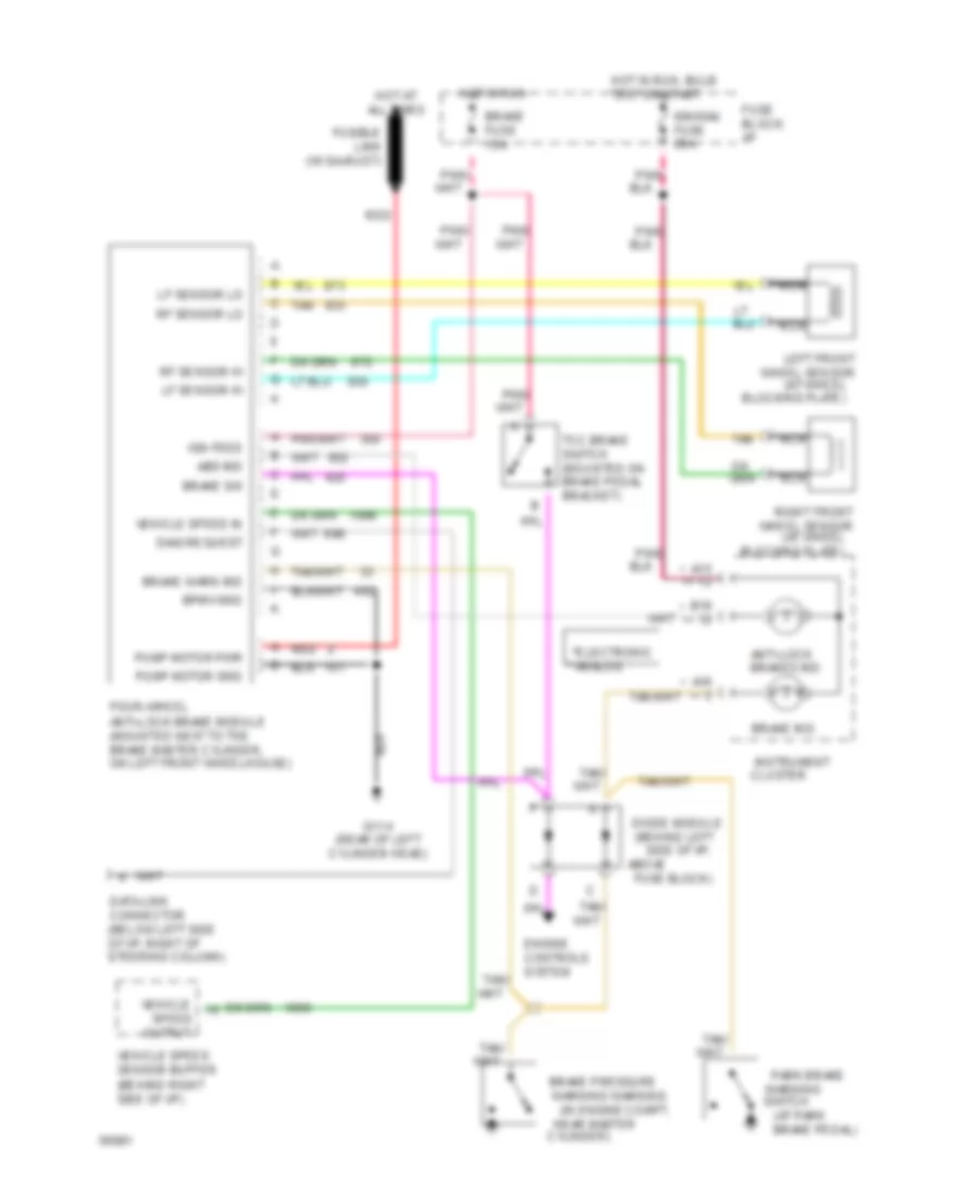
All-Wheel ABS Wiring Diagram for Oldsmobile Bravada 1994
List of elements for All-Wheel ABS Wiring Diagram for Oldsmobile Bravada 1994:
- (at park
- (at wheel
- (behind left side of i/p,
- * **
- **analog
- *electronic
- A15
- A16
- Above
- Abs ind
- Anti-lock brakes ind.
- B16
- Blocking plate)
- Bpmv gnd
- Brake fuse 15a
- Brake ind.
- Brake pedal)
- Brake pressure
- Brake sw
- Brake warn ind
- Cluster
- Cylinder)
- Data link connector (below left side of i/p, right of steering column)
- Diag request
- Diode module
- Engine controls system
- Four-wheel anti-lock brake module (mounted next to the brake master cylinder, on left front wheelhouse)
- Fuse block)
- Fuse block: i/p
- Fusible link (16 ga-rust)
- G114 (rear of left cylinder head)
- Hot at all times
- Hot in run
- Hot in run, bulb test or start
- Ign feed
- Ign/gau fuse 20a
- Instrument
- Left front wheel sensor
- Lf sensor hi
- Lf sensor lo
- Nca
- Near master
- Output
- Park brake
- Pnk/
- Pump motor gnd
- Pump motor pwr
- Red
- Rf sensor hi
- Rf sensor lo
- Right front wheel sensor
- Speed
- Switch
- Tan
- Tcc brake switch (mounted on brake pedal bracket)
- Vehicle
- Vehicle speed in
- Vehicle speed sensor buffer (behind right side of i/p)
- Warning
- Warning warning (in engine compt,
 English