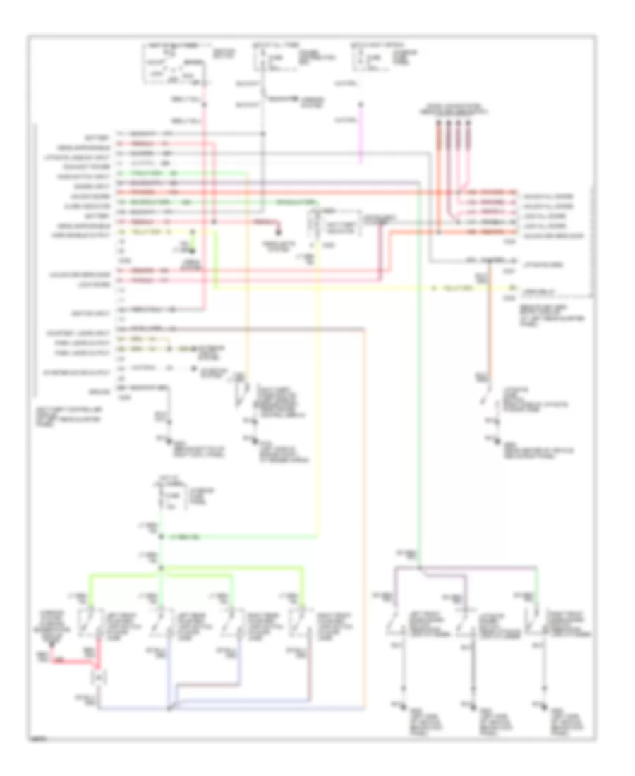
ANTI-THEFT
Anti-theft Wiring Diagram for Ford Explorer 1994
List of elements for Anti-theft Wiring Diagram for Ford Explorer 1994:
- Acc
- Alarm indicator
- Anti-theft controller module (at left rear quarter panel)
- Anti-theft hood switch (left side of engine compt, near cruise control servo)
- Anti-theft indicator
- Battery
- C222
- C336
- C337
- C338
- C339
- C340
- Courtesy lamps input
- Disarm input
- Door locks system (remote keyless entry)
- Exterior lights system
- Fuse 10a
- Fuse 15a
- Fuse 30a
- G104 (left side of engine compt., at fender apron)
- G200 (left side of vehicle, behind kick panel)
- G203 (behind bottom of right cowl panel)
- G909 (rear center of vehicle, above roof panel)
- Ground
- Headlamps enable
- Headlights system
- Hood switch input
- Horn enable output
- Horn relay
- Horns system
- Hot at all times
- Hot in accy or run
- Ignition input
- Ignition switch
- Instrument cluster
- Interior fuse panel
- Left front courtesy lamp switch (in door jamb)
- Left front door disarm switch (near door lock cylinder)
- Left rear courtesy lamp switch (in door jamb)
- Liftgate disarm switch (near liftgate lock cylinder)
- Liftgate jamb sw input
- Liftgate jamb switch (right side of liftgate, in door jamb)
- Liftgate open
- Lock
- Lock all doors
- Lock doors
- Mirrors system
- Off
- Park lamps output
- Power distribution box
- Red/ pnk
- Remote keyless entry module (at left rear quarter panel)
- Right front courtesy lamp switch (in door jamb)
- Right front door disarm switch (near door lock cylinder)
- Right rear courtesy lamp switch (in door jamb)
- Run
- Run/accy power
- Start
- Starter motor output
- Starting system
- Unlock all doors
- Unlock doors
- Unlock driver's door
- Warning system (warning buzzer/chime module pin #2)
 English