INSTRUMENT CLUSTER
Instrument Cluster Wiring Diagram for Ford Explorer 1994

List of elements for Instrument Cluster Wiring Diagram for Ford Explorer 1994:
- (at left rear
- (dimmer/flash
- (left side of engine compt, at fender apron)
- (left side of vehicle, behind kick panel)
- (not used)
- (right front
- (right rear corner of engine compt)
- (right side of i/p, right side of kick panel)
- (turn/hazard
- 4wabs control module (left rear corner of engine compt)
- 4wabs data link connector (left side of engine compt)
- 4x2
- 4x4
- 4x4 high
- 4x4 high range ind.
- 4x4 indicator switch (mounted on transfer case)
- 4x4 low
- 4x4 low range ind.
- A10
- A11
- A12
- A13
- A14
- Acc
- Alternator/
- Anti- lock brakes ind.
- Anti- slosh module
- Anti- theft ind.
- Anti-lock brakes system
- Anti-theft
- B10
- B11
- B12
- B13
- B14
- Bat
- Brake fluid level warning switch (on left side of brake master cylinder)
- Brake ind.
- Charge warning ind.
- Check oil ind.
- Conn
- Controller module
- Coolant temp.
- Coolant temp. gauge
- Drl module (left front corner of engine)
- Electronic shift
- Electronic shift control module (rear of vehicle, over wheel well)
- Electronic shift control switches (w/ electronic shift)
- Engine speed
- Exterior lights
- Exterior lights system (turn/ hazard switch)
- Fasten seat belts ind.
- Fuel gauge
- Fuel level
- Fuel pump/sender (at tank, in front
- Fuse 10a
- Fuse 15a
- Fuse 17- w/ limited edition & electronics group
- G104
- G200
- G201
- G203
- Gnd
- Headlights system
- Hi beam ind.
- Hot at all times
- Hot in run or start
- Hot w/ lamp switch in park or head
- Ign
- Ignition control module (right front corner of engine compt, left of headlamp)
- Ignition switch
- Illum.
- Illum. lamps
- Instrument cluster
- Interior fuse panel: i/p
- Left turn ind.
- Lock
- Low
- Low oil level relay (left side of dash, above interior fuse panel)
- Low oil level switch (left side of engine, at oil pan)
- Mal- function ind.
- Mechanical shift
- Of engine compt)
- Of rear axle)
- Off
- Ohms
- Oil press.
- Oil press. gauge
- Oil pressure switch (on engine, next to power steering pump)
- Parking brake switch
- Powertrain control module (under dash, at right kick panel)
- Quarter panel)
- Regulator
- Right turn ind.
- Run
- Start
- Switch)
- System
- Tacho- meter
- Tachometer test connector (right rear corner of engine compt, near blower motor)
- To pass switch)
- Vip data link connector
- Volt- meter
- W/ drl
- W/o drl
- Warning buzzer/ chime module (right side of i/p)
- Water temperature indicator sender (left front corner of engine)
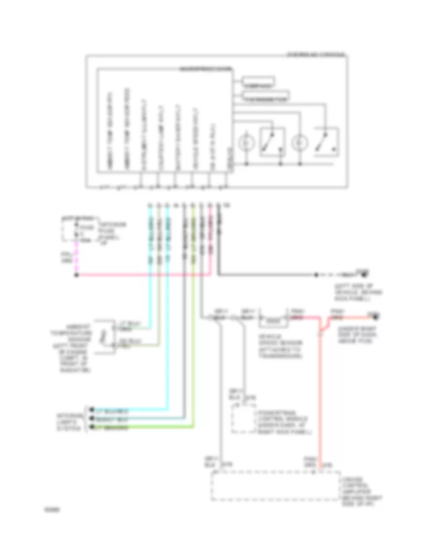
Overhead Console Wiring Diagram for Ford Explorer 1994
List of elements for Overhead Console Wiring Diagram for Ford Explorer 1994:
- (left front
- (left side of vehicle, behind kick panel)
- (under right side of dash, above pcm)
- Ambient
- Ambient temp sensor feed
- Ambient temp sensor rtn
- Battery saver input
- Compass
- Courtesy lamp input
- Cruise control amplifier (behind right side of i/p)
- Fuse 15a
- G200
- G201
- Ground
- Hot in run
- Ign (hot in run)
- Instrument illum input
- Interior fuse panel: i/p
- Interior lights system
- Microprocessor
- Of engine compt, in front of radiator)
- Overhead console
- Powertrain control module (under dash, at right kick panel)
- Sensor
- Temperature
- Thermometer
- Vehicle speed input
- Vehicle speed sensor (attached to transmission)