BODY COMPUTER
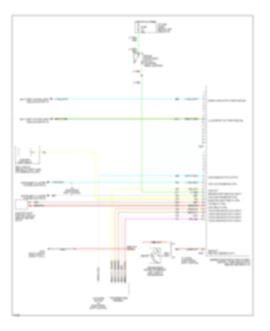
Body Computer Wiring Diagrams (1 of 2) for Ford Ranger 1996

List of elements for Body Computer Wiring Diagrams (1 of 2) for Ford Ranger 1996:
Body Computer Wiring Diagrams (2 of 2) for Ford Ranger 1996
List of elements for Body Computer Wiring Diagrams (2 of 2) for Ford Ranger 1996: