BODY COMPUTER
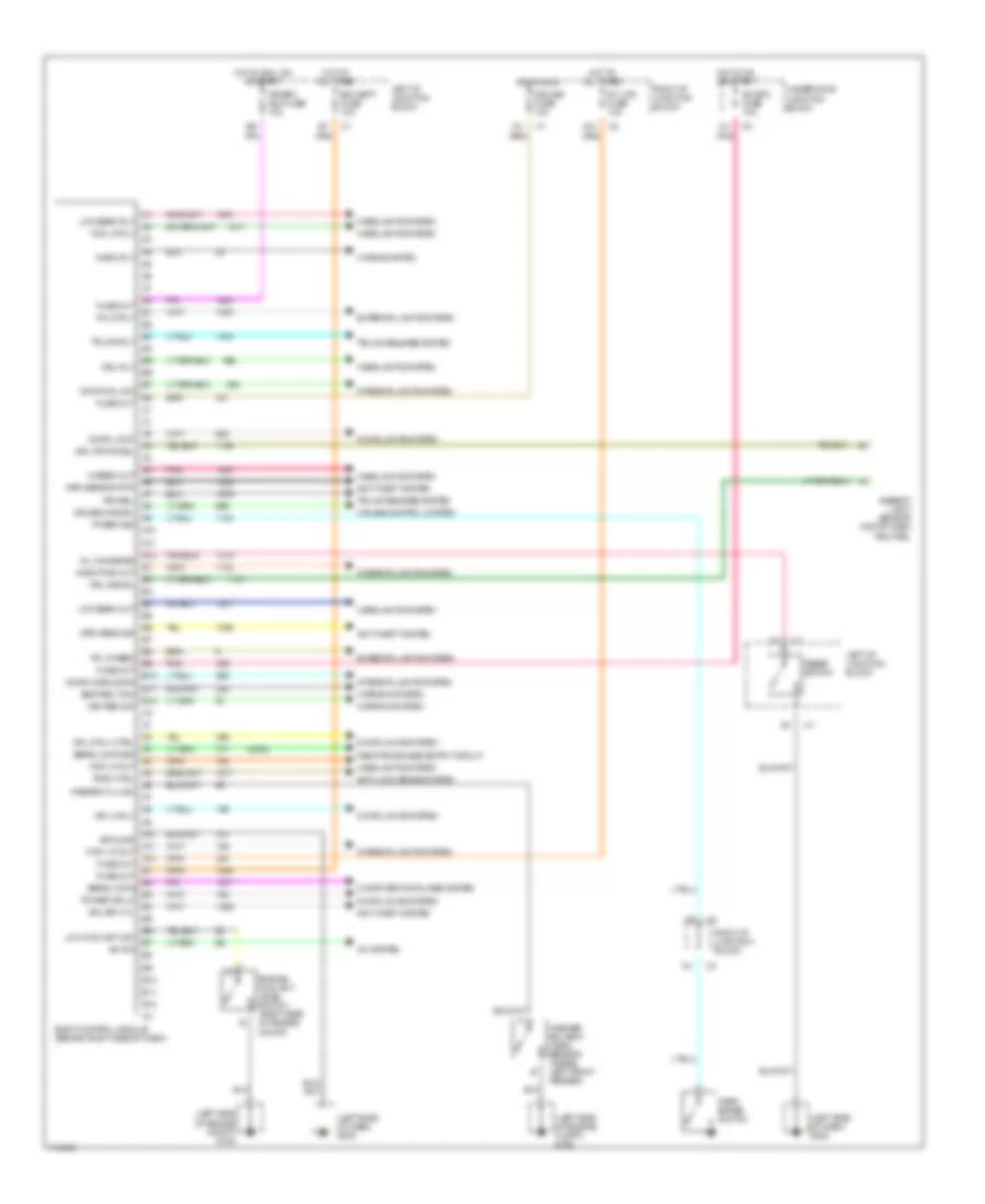
Body Computer Wiring Diagrams for Oldsmobile Alero GL 1999
List of elements for Body Computer Wiring Diagrams for Oldsmobile Alero GL 1999:
- (2000)
- (left side of dash) g202
- (left side of engine compt) g100
- A/c bfc fuse 10a
- A/c sw
- A/c system
- A10
- A11
- A12
- Ambient light sensor (top of dash trim pad)
- Anti-lock brake system
- Anti-theft system
- B10
- B11
- B12
- Bfc batt fuse 10a
- Body control module (behind right side of dash)
- Computer data lines system
- Cruise cancel
- Cruise control system
- Cruise fuse 10a
- Ctsy lp out
- Door handle sw
- Door hdl sw
- Door lock
- Door locks system
- Dr lk rly
- Dr lk rly ctrl
- Drl photocel
- Drl rly
- Drl signal
- Engine coolant level switch (right side of engine compt)
- Exterior lights system
- Fog lp out
- Fog lp rly
- Fuse out
- Ground
- Headlights system
- Hi beam out
- Horn rly
- Horns system
- Hot at all times
- Hot in acc, on or start
- Hot in on or start
- Hot in run
- Ign key cyl
- Inadv pwr out
- Int lps fuse 10a
- Interior lights system
- Ipc/bfc acc fuse 10a
- Key rem sw
- Left i/p junction block
- Low beam out
- Low beam rly
- Low coolant lev
- Mrd sens sig
- Mrd sensor rtn
- Oil chnge re
- Park brake switch
- Pk brk sig
- Pk lp feed
- Pk lp rly
- Pnk
- Power dr lk
- Remote keyless entry circuit
- Reset switch
- Right i/p junction block
- Seat belt sw
- Serial data
- Serial data sig
- Trac ctrl
- Trk rel
- Trunk release system
- Trunk rly
- Underhood junction block
- Warning system
- Washer flu lev
- Washer solvent level sensor (inside left front fender)
 English