COOLING FAN
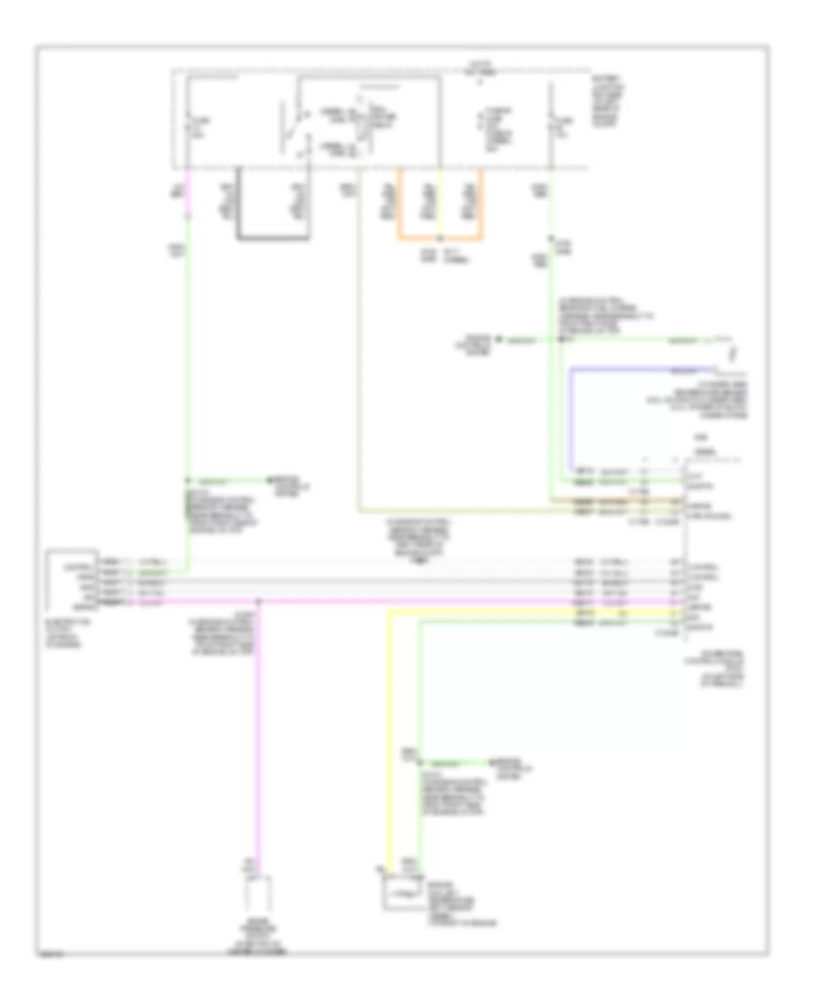
Cooling Fan Wiring Diagram for Ford F450 Super Duty 2008
List of elements for Cooling Fan Wiring Diagram for Ford F450 Super Duty 2008:
- (diesel)
- (diesel) (gas)
- (gas)
- (in engine control sensor & fuel charge harness, near breakout to front right side of engine, on top) s133
- (in engine control sensor harness, near breakout to front right side of engine, on top)
- (in engine control sensor harness, near breakout to right rear of engine compt) s1008
- Battery junction box (bjb) (at left rear of engine compt)
- Brake pressure switch (at bottom of master cylinder)
- C1232b
- C1232e
- C175b
- C175e
- Ce237
- Cec11
- Cht
- Control
- Cylinder head temperature sensor (6.8l: on right cylinder head) (5.4l: at rear of block, under intake)
- Diesel
- Electric fan clutch (at front of engine)
- Engine controls system
- Engine coolant temperature (ect) sensor (diesel) (at front of engine)
- Fuse 10a
- Fuse 20a
- Fuse 50 (gas) 30a fuse 39 (diesel) 50a
- Gas
- Gd119
- Gnd
- Hot at all times
- Kapwr
- Mpr (pcm-rc)
- Nca
- Pcm power relay
- Powertrain control module (pcm) (at left side of firewall)
- Re405
- S1009 (in engine control sensor harness, near breakout to front right side of engine, on top)
- S1013 (in engine control sensor harness, near breakout to front right side of engine, on top)
- S154 s117 (diesel)
- S158 (gas)
- Sbb36
- Sig
- Sig rtn
- Vbpwr
- Ve712
- Ve716
- Vec03
- Vec10
- Vpwr
 English