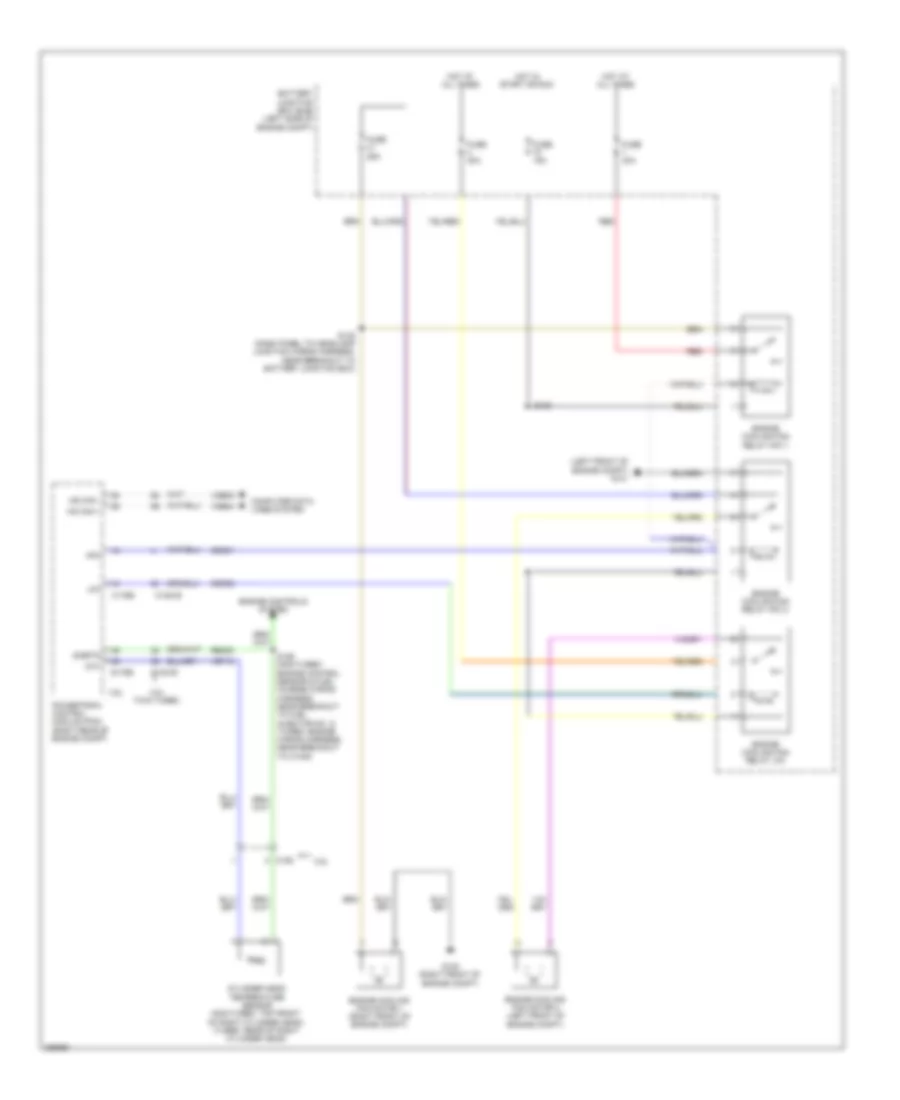
COOLING FAN
Cooling Fan Wiring Diagram for Ford Flex SEL 2013
List of elements for Cooling Fan Wiring Diagram for Ford Flex SEL 2013:
- (left front of engine compt) g101
- 3.5l
- 3.5l twin turbo
- Battery junction box (bjb) (left side of engine compt)
- C1381b
- C1381e
- C175b
- C175e
- C192
- Cec01
- Cec02
- Cht
- Computer data lines system
- Cylinder head temperature sensor (non-turbo: top front of right cylinder head) (turbo: rear of right cylinder head)
- Engine controls system
- Engine cooling fan motor 1 (right front of engine compt)
- Engine cooling fan motor 2 (left front of engine compt)
- Engine cooling fan relay hfc 1
- Engine cooling fan relay hfc 2
- Engine cooling fan relay lfc
- Fuse 15a
- Fuse 25a
- Fuse 40a
- G100 (right front of engine compt)
- Hfc
- Hot at all times
- Hot in start or run
- Hs can +
- Hs can -
- Lfc
- Powertrain control module (pcm) (right rear of engine compt)
- Re405
- Red
- S108
- S122 (dash panel to headlamp junction wiring harness, near breakout to battery junction box)
- S126 (non-turbo: engine control sensor & fuel charge wiring harness, near breakout to fuel injector no. 3) (turbo: engine wiring harness, near breakout to c1045)
- Sigrtn
- Vdb04
- Vdb05
- Ve712
 English