COOLING FAN
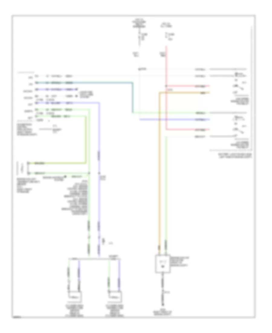
Cooling Fan Wiring Diagram for Ford Mustang GT 2012
List of elements for Cooling Fan Wiring Diagram for Ford Mustang GT 2012:
- 3.7l
- 5.4l
- Battery junction box (bjb) (left side of engine compt)
- C1026
- C1381b
- C1381e
- C175b
- C175e
- Cec01
- Cec02
- Cht
- Computer data lines system
- Cylinder head temperature sensor (rear of cylinder head)
- Ect
- Engine controls system
- Engine coolant temperature (ect) sensor (5.4l) (right front of engine)
- Engine cooling fan motor (front of engine compt)
- Except 3.7l
- Except 5.4l
- Fuse 40a
- Fuse 5a
- G100 (right front of engine compt)
- Hfc
- High speed engine cooling fan relay
- Hot at all times
- Hot w/ pcm power relay energized
- Hs can+
- Hs can-
- Lfc
- Low speed engine cooling fan relay
- Nca
- Powertrain control module (pcm) (right front of engine compt)
- Re141
- Re405
- S102 (5.0l & 5.4l) (5.0l: engine control sensor & fuel charge harness, near breakout to c1019) (5.4l: engine control sensor & fuel charge harness, near breakout to ignition transformer capacitor 1)
- S106 (5.4l)
- S112
- S121
- S125
- Sigrtn
- Vdb04
- Vdb05
- Ve712
 English