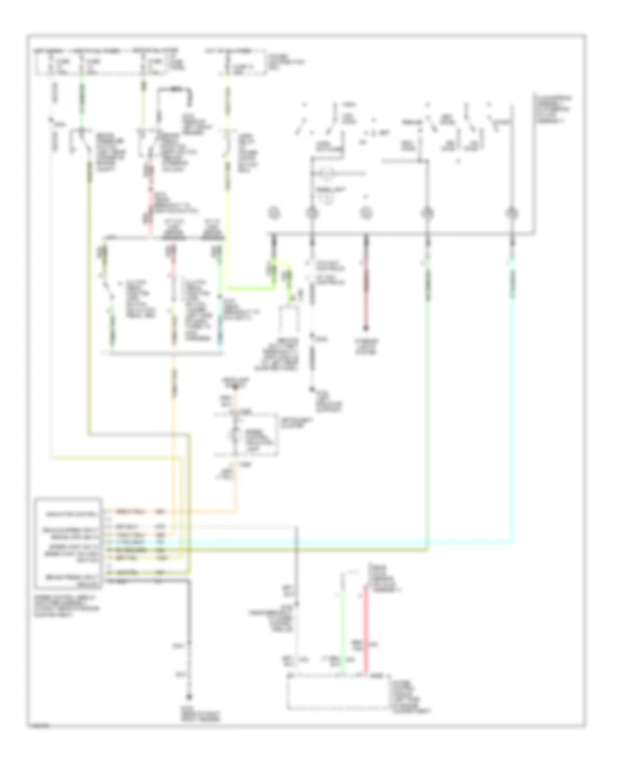
CRUISE CONTROL
Cruise Control Wiring Diagram for Ford Explorer 1998
List of elements for Cruise Control Wiring Diagram for Ford Explorer 1998:
- (w/ aux controls)
- (w/o aux controls)
- 4wabs control module (left side of engine compartment)
- A/t w/ high series console
- A/t w/o high series console
- Accel
- Back light
- Brake pedal position (bpp) switch (behind steering column)
- Brake press input
- Brake pressure switch (left rear corner of engine compt)
- C186
- C286
- C338
- Clockspring assembly (in steering column assembly)
- Clutch pedal position (cpp) switch (on clutch pedal arm)
- Clutch pedal position (cpp) switch jumper (left side of dash, taped to main harness)
- Coast
- Fuse 10 15a
- Fuse 20a
- Fuse 7.5a
- G104 (rear of left front fender)
- G105 (rear of right front fender)
- G108 (left radiator support)
- Ground
- Headlamp switch
- Horn relay (in power distri- bution box)
- Horn switches
- Hot at all times
- Hot in run
- I/p fuse panel
- Ignition
- Indicator control
- Instrument cluster
- Interior lights system
- M/t
- Nca
- Off
- Ohms
- Pnk
- Power distribution box
- Rear axle sensor (on axle assembly)
- Red/
- Red/ lt grh
- Remote anti-theft personality (rap) module (at left rear quarter panel)
- Resume
- S161
- S168 (near breakout to 4wabs control module)
- S215 (near breakout to ignition switch)
- S230
- S232
- S244
- Set/
- Speed cont sw gnd
- Speed cont sw in
- Speed control indicator lamp
- Speed control servo/ amplifier assembly (in right rear of engine compartment)
- Vehicle speed input
 English