CRUISE CONTROL
6.8L
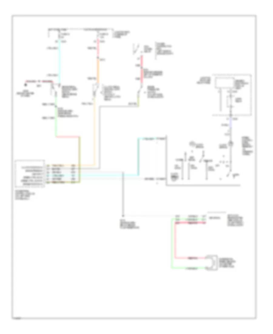
6.8L, Cruise Control Wiring Diagram for Ford F550 Super Duty 1999

List of elements for 6.8L, Cruise Control Wiring Diagram for Ford F550 Super Duty 1999:
- 10a
- 20a
- A/t
- Accel
- Anti-lock brake system (abs) module (in left front of eng compt)
- Brake pedal position (bpp) switch (above brake pedal)
- Brake press in
- Brake pressure switch (on left side of eng compt)
- Brake/clutch sw in
- C242
- C243
- Clock spring
- Clutch pedal position (cpp) switch (above clutch pedal)
- Clutch pedal position (cpp) switch jumper (above clutch pedal)
- Coast
- Differential speed sensor (on center of rear axle)
- Fuse 13
- Fuse 15
- Fuse 28
- G101 (front of right front fender)
- G206 (behind center of dash)
- Generic electronic module (gem)
- Ground
- Horn
- Horn relay
- Hot at all times
- Hot in run
- Junction box fuse/ relay panel
- Junction box fuse/relay panel
- M/t
- Nca
- Off
- Ohms
- Power
- Red/pnk
- Resume
- S115 (engine harn, below brake fluid reservoir)
- S124
- S180
- S201
- S205 (main harness, left of steering column)
- Set/
- Speed control servo/ amplifier assembly (in right side of engine compt)
- Speed control/ horn switch assembly (in steering wheel)
- Speed ctrl sw in
- Speed ctrl sw rtn
- Vss input
- Vss signal
7.3L DI TURBO DIESEL
7.3L DI Turbo Diesel, Cruise Control Wiring Diagram for Ford F550 Super Duty 1999
List of elements for 7.3L DI Turbo Diesel, Cruise Control Wiring Diagram for Ford F550 Super Duty 1999:
- 10a
- Accel
- Anti-lock brake system (abs) module (in left front of eng compt)
- Brake pedal position (bpp) switch (above brake pedal)
- Brake position in
- Brake press in
- Brake pressure switch (on left side of eng compt)
- C242
- C243
- Clock spring
- Clutch pedal position (cpp) switch (m/t only) (above clutch pedal)
- Clutch position in
- Coast
- Differential speed sensor (on center of rear axle)
- Fuse 15
- Fuse 19
- G206 (behind center of dash)
- Generic electronic module (gem)
- Horn
- Horn relay
- Hot at all times
- Hot in start or run
- Junction box fuse/ relay panel
- Junction box fuse/relay panel
- Nca
- Off
- Ohms
- Pcm power relay
- Power distribution box (left side of engine compt)
- Powertrain control module (on left side of firewall)
- Red
- Red/pnk
- Resume
- S108 (engine harn, near brake pressure switch)
- S115 (engine harn, below brake fluid reservoir)
- S123 (engine harness, left of steering column)
- S201
- S213
- Set/
- Speed control/ horn switch assembly (in steering wheel)
- Speed ctrl sw in
- Speed ctrl sw rtn
- Vss input
- Vss signal