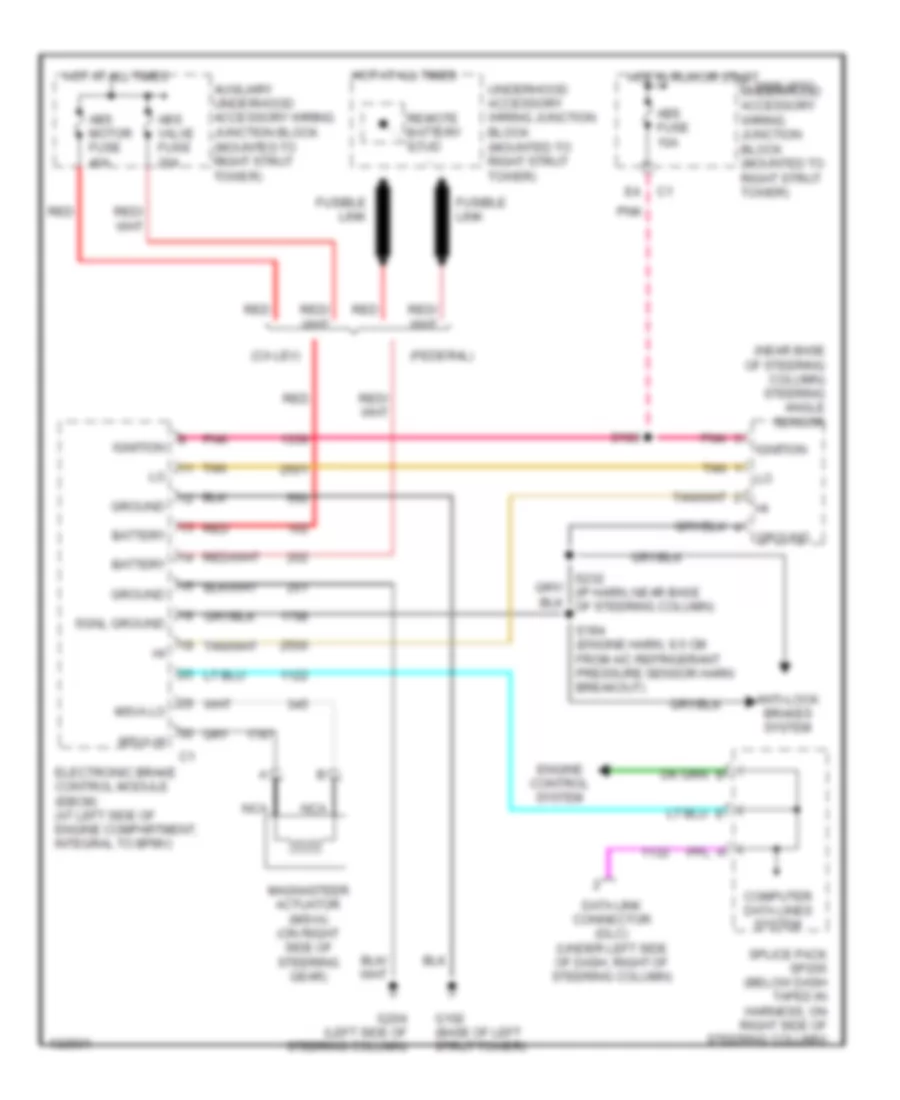
ELECTRONIC POWER STEERING
Electronic Power Steering Wiring Diagram for Oldsmobile Intrigue GLS 2000
List of elements for Electronic Power Steering Wiring Diagram for Oldsmobile Intrigue GLS 2000:
- (ca lev)
- (federal)
- (near base of steering column) steering angle sensor
- 1995 vftc c underhood accessory wiring junction block (mounted to right strut tower)
- Abs fuse 10a
- Abs motor fuse 40a
- Abs valve fuse 20a
- Anti-lock brakes system
- Auxiliary underhood accessory wiring junction block (mounted to right strut tower)
- Battery
- Computer data lines system
- Data link connector (dlc) (under left side of dash, right of steering column)
- Electronic brake control module (ebcm) (at left side of engine compartment, integral to bpmv)
- Engine control system
- Fusible link
- G102 (base of left strut tower)
- G204 (left side of steering column)
- Ground
- Hot at all times
- Hot in run or start
- Ignition
- Magnasteer actuator (msva) (on right side of steering gear)
- Msva hi
- Msva lo
- Nca
- Pnk
- Red
- Remote battery stud
- S183
- S184 (engine harn, 9.5 cm from a/c refrigerant pressure sensor harn breakout)
- Sgnl ground
- Splice pack sp205 (below dash taped in harness, on right side of steering column)
- Tan
- Underhood accessory wiring junction block (mounted to right strut tower)
 English