ELECTRONIC SUSPENSION
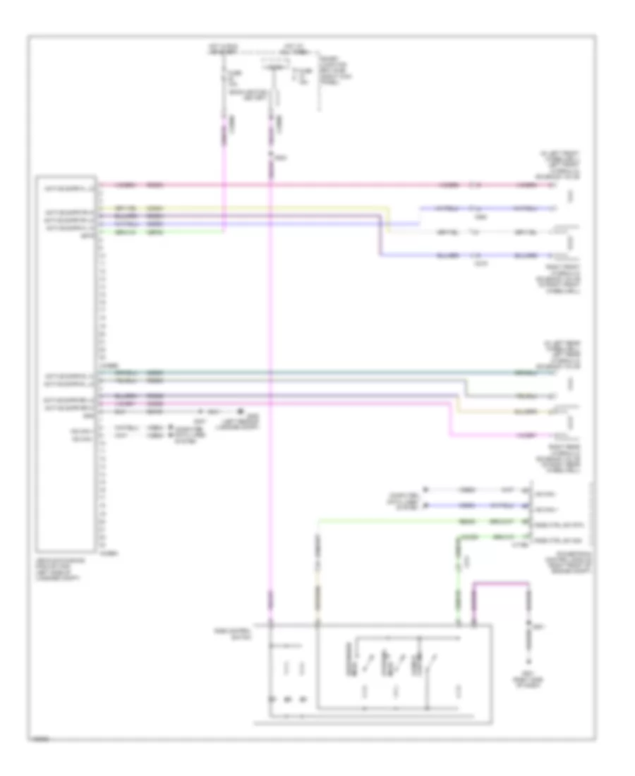
Electronic Suspension Wiring Diagram for Ford Mustang Shelby GT500 2014
List of elements for Electronic Suspension Wiring Diagram for Ford Mustang Shelby GT500 2014:
- (in left front wheelwell) left front hydraulic solenoid valve
- (in left rear wheelwell) left rear hydraulic solenoid valve
- Active dmpr fl hi
- Active dmpr fl lo
- Active dmpr fr hi
- Active dmpr fr lo
- Active dmpr rl hi
- Active dmpr rl lo
- Active dmpr rr hi
- Active dmpr rr lo
- Backlighting led (fet)
- C175b
- C211
- C219
- C2280b
- C2280d
- C264
- C4396a
- C4396b
- Cbp32
- Ccd03
- Ccd04
- Ccd05
- Ccd06
- Cmc29
- Computer data lines system
- Control launch
- Fuse 10a
- Fuse 15a
- G201 (right side of dash)
- G400 (left rear of luggage compt)
- Gd109
- Gnd
- Hot at all times
- Hot in run or start
- Hs can +
- Hs can -
- Isp-r
- Micro
- Powertrain control module (right front of engine compt)
- Rcd03
- Rcd04
- Rcd05
- Rcd06
- Re405
- Ride control switch
- Ride ctrl sw rtn
- Ride ctrl sw sig
- Right front hydraulic solenoid valve (in right front wheelwell)
- Right rear hydraulic solenoid valve (in right rear wheelwell)
- S201
- S224
- S407
- Smart junction box (sjb) (right kick panel)
- Steering mode
- Suspension mode
- Vdb04
- Vdb05
- Vehicle dynamics module (vdm) (left side of luggage compt)
 English