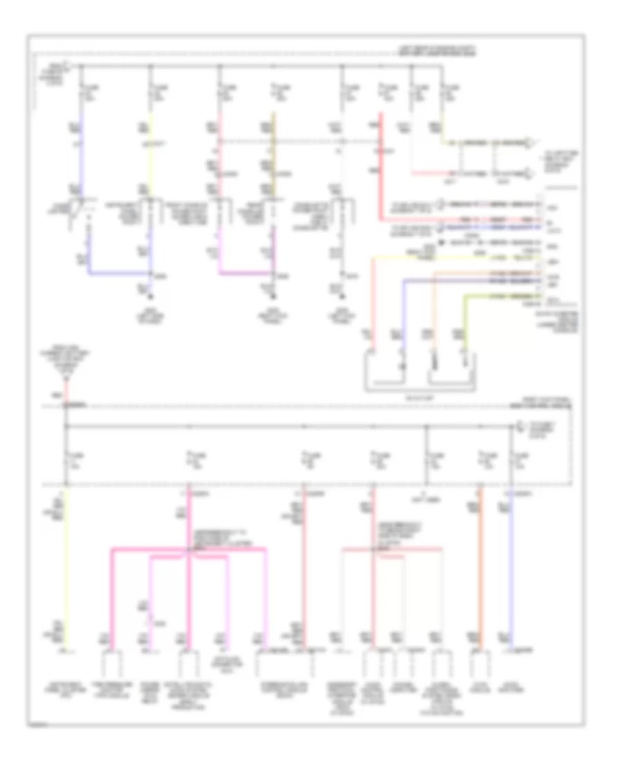
БЛОК ПРЕДОХРАНИТЕЛЕЙ И РЕЛЕ
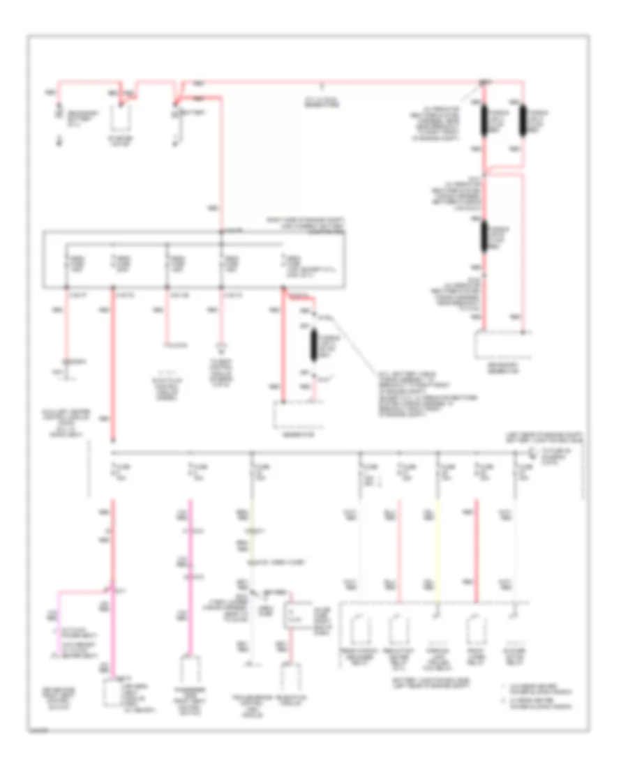
Электросхема блока предохранителей и реле (1 из 9) для Ford Cab amp; Chassis F350 Super Duty 2011
Электросхема блока предохранителей и реле (1 из 9) для Ford Cab amp; Chassis F350 Super Duty 2011 - Список элементов:
- (6.7l: battery cable wiring assembly, in breakout to right front of engine compt) (except 6.7l: alternator rectifier system wiring harness, in breakout right front of engine compt)
- (alternator rectifier system harness, near near breakout to right front of engine compt)
- (crew chief)
- (except 6.7l) (6.7l)
- (left rear of engine compt) battery junction box (bjb)
- (right side of engine compt) high current battery junction box
- (w/ 6 way
- (w/o memory w/ 10 way power seat)
- 6.7l w/ dual generators
- Auxiliary heater control module (ahcm) (6.7l w/ rapid heat)
- Battery
- Battery junction box (bjb) (left rear of engine compt)
- Blower motor relay
- C1273a
- C1617a
- C1617b
- C1617c
- C1617d
- C1617e
- C1617f
- C210
- C2108
- C211
- C2463a
- C311
- C312
- C341a
- Crew chief
- Driver side front seat control switch
- Driver's seat module (dsm) (w/ memory)
- Front wiper relay
- Fuse 25a
- Fuse 30a
- Fuse 40a
- Fuse 40a 50a
- Fusible link b (12 ga- red)
- Fusible link c (12 ga- red)
- Fusible link d (12 ga- red)
- Generator
- Glow plug control module (diesel)
- Inline fuse (right end of dash)
- Mega fuse 125a
- Mega fuse 175a 275a
- Mega fuse 200a
- Nca
- Parking lamp trailer tow relay
- Passenger side front seat control switch
- Power seat)
- Rear window defogger relay
- Red
- Reductant heater relay (6.7l)
- S137
- S138
- S139
- S140 (alternator rectifier system wiring harness, near breakout to c144)
- S141 (alternator rectifier system wiring harness, between fusible link b & c)
- S272 (t-box jumper wiring harness, near t/o to c2108)
- Secondary battery (6.7l)
- Secondary generator
- Starter motor
- Telematics module
- To body control module (diagram 5 of 9)
- To fuse 39 (diagram 2 of 9)
- Trailer brake control (tbc) module
- W/ rear heated power sliding window
- W/o rear heated power sliding window
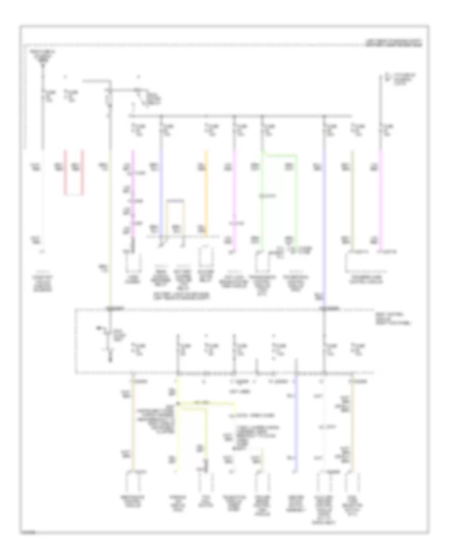
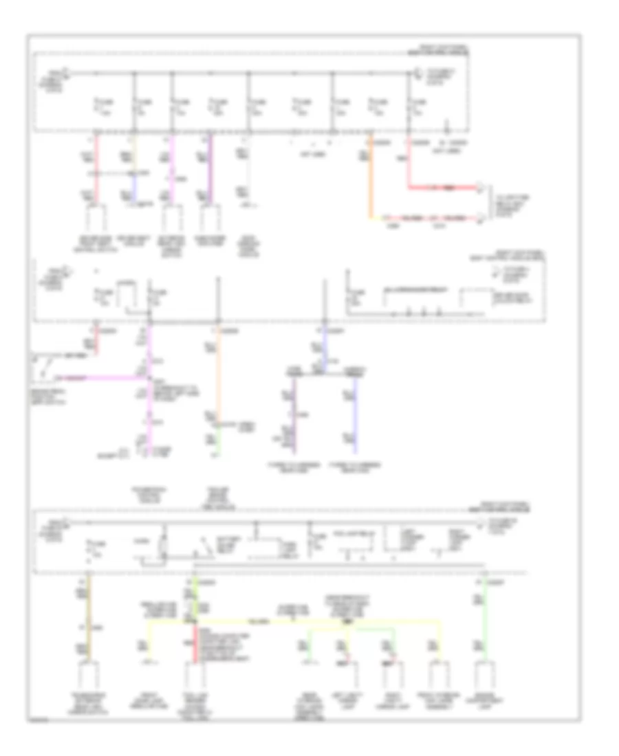
Электросхема блока предохранителей и реле (2 из 9) для Ford Cab amp; Chassis F350 Super Duty 2011
Электросхема блока предохранителей и реле (2 из 9) для Ford Cab amp; Chassis F350 Super Duty 2011 - Список элементов:
- (crew chief)
- (left rear of engine compt) battery junction box (bjb)
- (not used)
- (t-box jumper wiring harness, near breakout to c2108) (crew chief) s274
- 6.7l except 6.7l
- Anti-lock brake system (abs) module
- Auxiliary heater control module (ahcm) (6.7l w/ rapid heat)
- Battery charge trailer tow relay
- Battery junction box (bjb) (left rear of engine compt)
- Blower motor relay
- Body control module (right kick panel)
- C1010
- C1232b
- C140
- C1581
- C175b
- C2108
- C214
- C2280b
- C2280d
- C2280e
- C2280f
- C2371a
- C2371b
- C2463b
- C310a
- C465
- C497
- Center stack switch assembly
- Constant vacuum hublock solenoid
- From fuse 23 (diagram 1 of 9)
- Fuel tank selector switch (6.7l)
- Fuse 10a
- Fuse 15a
- Fuse 20a
- Fuse 5a
- Fuse 7.5a
- Micro
- Nca
- Parking aid module (pam)
- Powertrain control module (pcm)
- Rear window defogger relay
- Restraints control module
- Run/ start (fet)
- Run/ start relay
- S227 (instrument panel wiring harness, near breakout to right side of instrument cluster)
- Telematics module (crew chief)
- To fuse 46 (diagram 3 of 9)
- Tow haul switch
- Trailer brake control (tbc) module
- Transfer case control module
- Transmission control module (tcm) (6.7l)
- Video camera
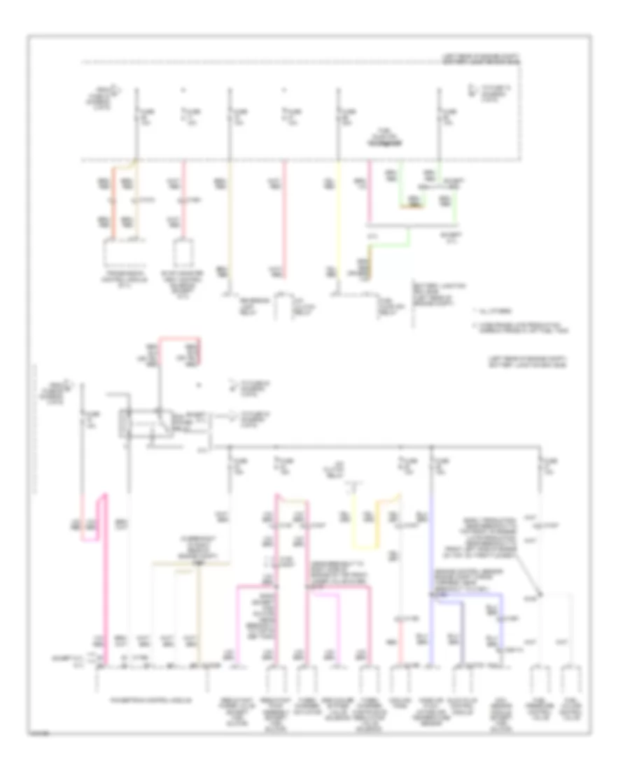
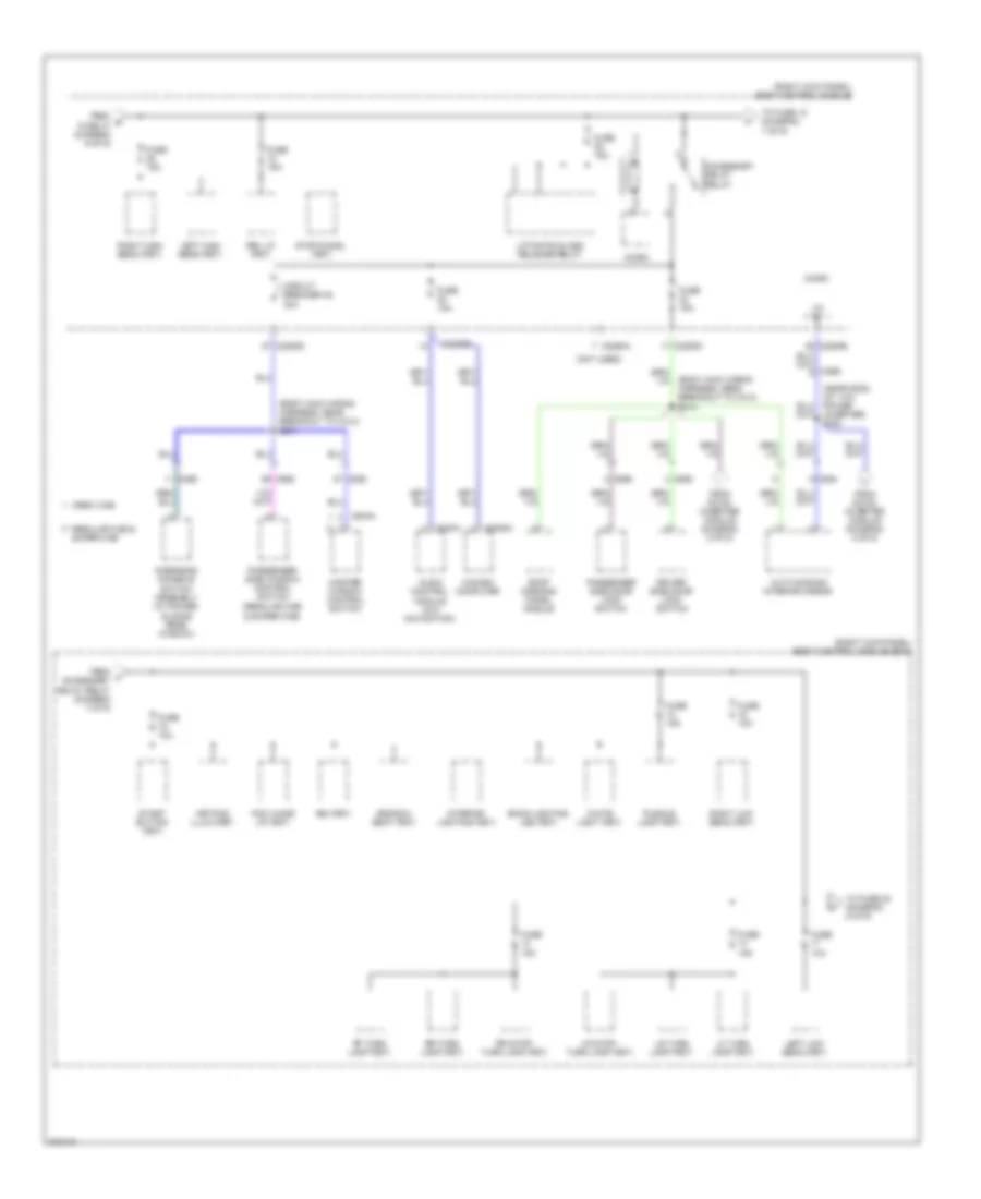
Электросхема блока предохранителей и реле (3 из 9) для Ford Cab amp; Chassis F350 Super Duty 2011
Электросхема блока предохранителей и реле (3 из 9) для Ford Cab amp; Chassis F350 Super Duty 2011 - Список элементов:
- (early production: near breakout to top front of engine) (late production: near breakout to front left side of engine on top, on throttle body)
- (engine control sensor engine compt wiring harness, near breakout to c1581) s122
- (in breakout to right rear of engine compt) s105
- (left rear of engine compt) battery junction box (bjb)
- (near breakout to right side of engine on top front, under valve cover) s110
- 6.7l
- A/c clutch relay
- All others
- Battery junction box (bjb) (left rear of engine compt)
- C1010
- C1047
- C115b
- C1165
- C1232b
- C1273c
- C139
- C140
- C1581
- C175b
- C3047
- C3611a
- Cooling fans
- Egr cooler bypass valve solenoid
- Evap canister vent control solenoid (except 6.7l)
- Except 6.7l
- From c fuse 40 (diagram 2 of 9)
- From d fuse 68 (diagram 3 of 9)
- Fuel pressure control valve
- Fuel pump (fp) motor diode
- Fuel pump (fp) relay
- Fuel volume control valve
- Fuse 10a
- Fuse 15a
- Fuse 20a
- Glow plug control module
- Mass air flow/ intake air temperature sensor
- Nca
- Nox sensor module (except high sulfur)
- Pcm power relay
- Powertrain control module
- Red
- Reductant pump assembly (except high sulfur)
- Reductant purge valve (except high sulfur)
- Reversing lamp relay
- S109
- S3000 (except high sulfur) (near breakout to top of def tank)
- To fuse 33 (diagram 4 of 9)
- To fuse 72 (diagram 3 of 9)
- To fuse 84 (diagram 4 of 9)
- Transmission control module (6.7l)
- Turbo charger actuator
- Turbo charger waste gate regulator valve solenoid
- Wide frame/late production narrow frame w/ aft fuel tank
Электросхема блока предохранителей и реле (4 из 9) для Ford Cab amp; Chassis F350 Super Duty 2011
Электросхема блока предохранителей и реле (4 из 9) для Ford Cab amp; Chassis F350 Super Duty 2011 - Список элементов:
- (6.8l)
- (6.8l: near breakout to top left rear of engine) (6.2l: near breakout to top right rear of engine) (6.8l) s135 (6.2l) s114
- (6.8l: near breakout to top right front of engine) (6.2l: near breakout to top right rear of engine) (6.8l) s127 (6.2l) s118
- (engine control sensor & fuel charge wiring harness, near breakout to c133)
- (engine control sensor & fuel charge wiring harness, near breakout to top right front of engine) s112
- (engine control sensor engine compt wiring harness, near breakout to c1581)
- (left rear of engine compt) battery junction box (bjb)
- (near breakout to left front corner of vehicle) s101
- (not used)
- (passenger cushion wiring harness, near breakout to bottom of passenger's seat)
- (transmission wiring harness, near breakout to right side of transmission) (6.2l) s181
- 6.2l
- 6.8l
- A/c clutch relay
- Anti-lock brake system (abs) module
- Battery charge trailer tow relay
- Battery junction box (bjb) (left rear of engine compt)
- C1168
- C1220
- C145
- C1581
- C175b
- C2371b
- C312
- C3265a e
- Coil on plug (cop) 1
- Coil on plug (cop) 10 (6.8l)
- Coil on plug (cop) 2
- Coil on plug (cop) 3
- Coil on plug (cop) 4
- Coil on plug (cop) 5
- Coil on plug (cop) 6
- Coil on plug (cop) 7
- Coil on plug (cop) 8
- Coil on plug (cop) 9 (6.8l)
- Cooling fan
- Dual climate controlled seat module
- Evaporative emission canister purge valve
- From e fuse 72 (diagram 3 of 9)
- From g fuse 34 (diagram 4 of 9)
- From pcm f power relay (diagram 3 of 9)
- Fuse 10a
- Fuse 15a
- Fuse 20a
- Fuse 25a
- Fuse 30a
- Fuse 40a
- Fuse 50a
- Heated oxygen sensor (ho2s) 12 (6.2l)
- Heated oxygen sensor (ho2s) 13 (narrow frame)
- Heated oxygen sensor (ho2s) 22 (6.2l)
- Ignition transformer capacitor 1
- Intake manifold tuning valve (imtv)
- Left turn trailer tow relay
- Mass air flow/ intake air temperature (maf/iat) sensor
- Not used
- Powertrain control module
- Red
- Right turn trailer tow relay
- S104
- S117
- S341
- Starter relay
- To fuse 35 (diagram 4 of 9)
- To fuse 83 (diagram 5 of 9)
- Transfer case control module (tccm)
- Universal heated oxygen sensor (ho2s) 11 (6.2l)
- Universal heated oxygen sensor (ho2s) 11 (6.8l)
- Universal heated oxygen sensor (ho2s) 21
- Variable camshaft timing solenoid 1
- Variable camshaft timing solenoid 2
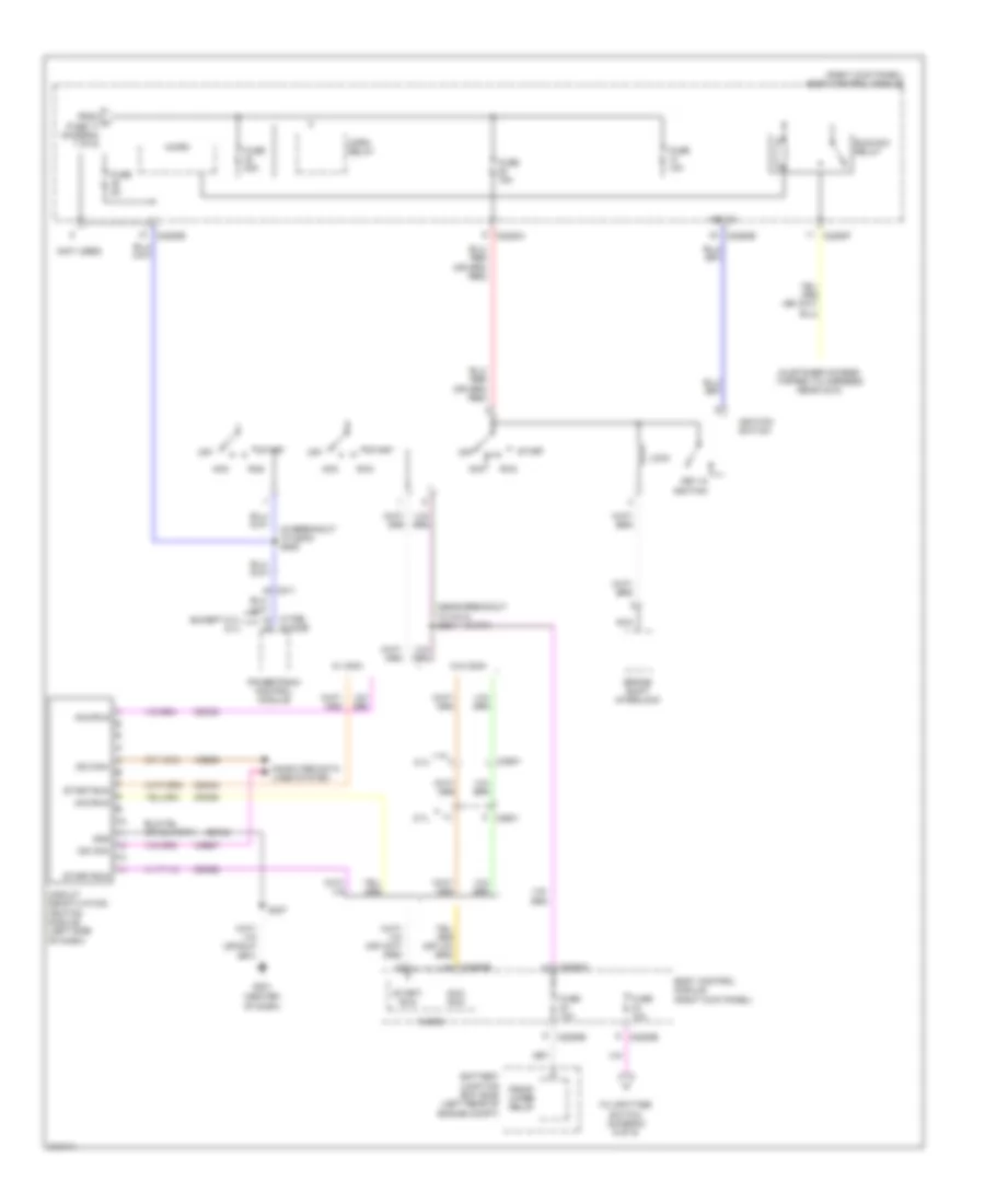
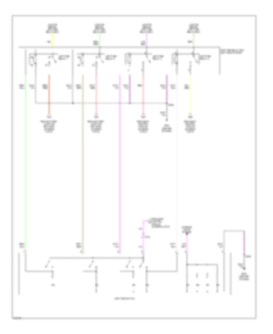
Электросхема блока предохранителей и реле (5 из 9) для Ford Cab amp; Chassis F350 Super Duty 2011
Электросхема блока предохранителей и реле (5 из 9) для Ford Cab amp; Chassis F350 Super Duty 2011 - Список элементов:
- (left rear of engine compt) battery junction box (bjb)
- (near breakout to behind right side of dash)
- (near breakout to right side of instrument cluster) s228
- (not used)
- (right kick panel) body control module
- (w/ sync) s222
- Ac outlet
- Ac-a
- Ac-b
- Acc
- Accessory protocol interface module (apim) (w/ sync)
- Audio amplifier
- Audio control module (w/ sync)
- C210
- C211
- C215
- C2280a
- C2280b
- C2280g
- C238
- C2385b
- C2408a
- C240a
- C2414a
- C2414b
- C3052
- C3501a
- C3501b
- Cbp32
- Cigar lighter
- Consolette power point (crew cab w/ consolette)
- Datalink connector (dlc)
- Dc/ac inverter module (under center console)
- From h fuse 90 (diagram 4 of 9)
- From high current battery junction box (diagram 1 of 9)
- Front console power point (super cab & crew cab)
- Fuse 10a
- Fuse 15a
- Fuse 20a
- Fuse 25a
- Fuse 40a
- Fuse 5a
- G203 (left side of dash)
- G300 (left kick panel)
- G302 (right kick panel)
- Gd179
- Global positioning system (gpsm) module (w/ sync w/o navigation)
- Gnd
- Hot
- Hvac module
- Hya01
- Hya02
- In-dash computer
- Instrument panel cluster (ipc)
- Instrument panel power point
- Led+
- Led-
- Lin 01
- Lya03
- Neut
- Power mirror fold relay
- Rear console power point
- Red
- Rya03
- S286
- S375
- S390
- Satellite digital audio system (sdars) module (early production)
- Sbb97
- Steering column control module (sccm)
- Tire pressure monitor (tpm) module
- To fuse 7 (diagram 6 of 9)
- To splice s314 (diagram 7 of 9)
- To splice s383 (diagram 7 of 9)
- To upfitter relay box (diagram 9 of 9)
- Vdn01
Электросхема блока предохранителей и реле (6 из 9) для Ford Cab amp; Chassis F350 Super Duty 2011
Электросхема блока предохранителей и реле (6 из 9) для Ford Cab amp; Chassis F350 Super Duty 2011 - Список элементов:
- (crew chief)
- (near breakout to bottom of passenger's seat)
- (near breakout to rear of roof) (super cab & crew cab) s908
- (not used)
- (right kick panel) body control module
- (right kick panel) body control module (bcm)
- (taped to harness near c422)
- (taped to harness near c465)
- 6.7l except 6.7l
- All lock/unlock relay
- Battery saver relay
- Brake pedal position (bpp) switch
- C1232b
- C175b
- C210
- C2108
- C212
- C215
- C2280b
- C2280d
- C2280f
- C265
- C300
- C341b
- C465
- C555
- Driver door unlock relay
- Driver seat module
- Driver side front seat control switch
- Engine compartment lamp
- Exterior rear view mirror switch
- Fog lamp relay
- From n fuse 27 (diagram 5 of 9)
- From o fuse 9 (diagram 6 of 9)
- From r fuse 20 (diagram 6 of 9)
- Front dome lamp (regular cab)
- Front interior/ map lamps assembly
- Fuse 10a
- Fuse 15a
- Fuse 20a
- Fuse 30a
- Fuse 5a
- Fuse 7.5a
- Left corner lamp (fet)
- Left vanity mirror lamp
- Micro
- Narrow frame
- Not used
- Park lamp relay
- Powertrain control module
- Rear interior/ map lamps assembly (crew cab)
- Red
- Regular cab super cab & crew cab
- Right corner lamp (fet)
- Right vanity mirror lamp
- Roof opening panel module
- S207 (in breakout to behind left side of dash)
- S350 (in-dash computer computer link) red
- Subwoofer amplifier
- Super cab & crew cab
- Telescoping exterior rear view mirror switch
- To fuse 21 (diagram 6 of 9)
- To fuse 39 (diagram 7 of 9)
- To fuse 4 (diagram 6 of 9)
- To upfitter relay box (diagram 9 of 9)
- Tool link reader (in-dash computer w/ tool link)
- Trailer brake control (tbc) module
- Wide frame
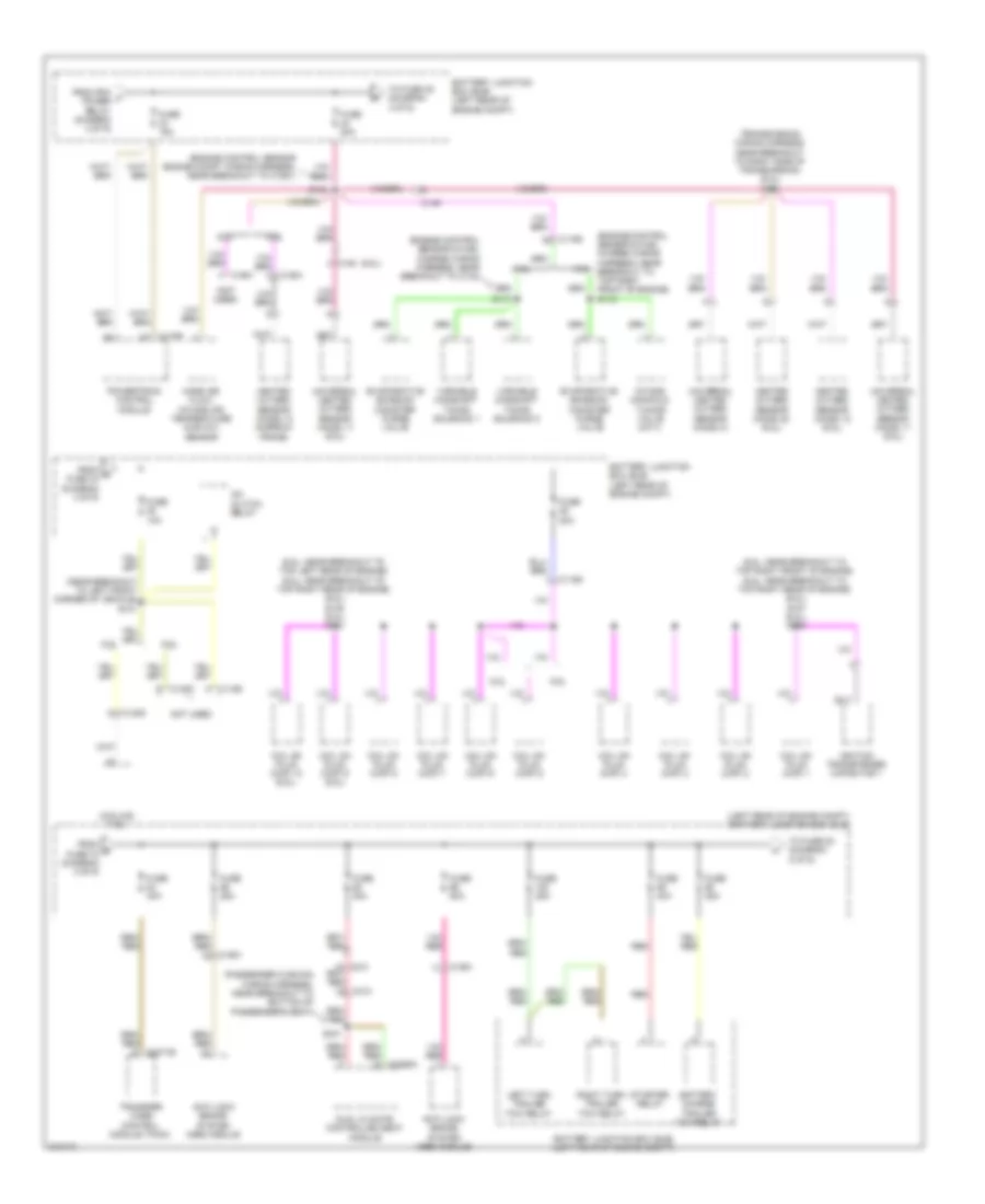
Электросхема блока предохранителей и реле (7 из 9) для Ford Cab amp; Chassis F350 Super Duty 2011
Электросхема блока предохранителей и реле (7 из 9) для Ford Cab amp; Chassis F350 Super Duty 2011 - Список элементов:
- (body main wiring harness, near breakout to c312) s314
- (body main wiring harness, near breakout to c312) s371
- (near g302) (w/ 110v power inverter) s383
- (not used)
- (regular cab & super cab)
- (right kick panel) body control module
- (right kick panel) body control module (bcm)
- 3rd row seat (fet)
- Accessory delay relay
- Audio control module (w/o navigation)
- Auto dimming interior mirror
- Back-lighting led (fet)
- Bsi (fet)
- C2280a
- C2280b
- C2280d
- C2408a
- C240a
- C264
- C265
- C268
- C504a
- C555
- C655
- Circuit breaker 48 30a
- Crew cab
- Driver side door lock switch
- From dc/ac inverter module (diagram 5 of 9)
- From s fuse 47 (diagram 6 of 9)
- From t accessory delay relay (diagram 7 of 9)
- Fuse 10a
- Fuse 15a
- In-dash computer
- Interior lighting (fet)
- Keypad illum (fet)
- Left high beam (fet)
- Left low beam (fet)
- Lf turn lamp (fet)
- Liftgate glass release relay
- Lin
- Lr stop/ turn lamp (fet)
- Lr turn lamp (fet)
- Master window control switch
- Micro
- Overhead console switch assembly (w/ power sliding rear window)
- Passenger side door lock switch
- Passenger side window control switch
- Pcm wake up (fet)
- Puddle lamp (fet)
- Regular cab & super cab
- Rev lp (fet)
- Rf turn lamp (fet)
- Right high beam (fet)
- Right low beam (fet)
- Roof opening panel module
- Rr stop/ turn lamp (fet)
- Rr turn lamp (fet)
- Start button (fet)
- Stop/chmsl (fet)
- To fuse 18 (diagram 7 of 9)
- To fuse 22 (diagram 8 of 9)
- White light (fet)
Электросхема блока предохранителей и реле (8 из 9) для Ford Cab amp; Chassis F350 Super Duty 2011
Электросхема блока предохранителей и реле (8 из 9) для Ford Cab amp; Chassis F350 Super Duty 2011 - Список элементов:
- (center of dash)
- (customer access tapped to harness near c210)
- (in breakout to g203) s285
- (near breakout to c213) s284
- (not used)
- (right kick panel) body control module
- 6.7l
- Acc
- Acc/ run
- Acc/run
- Battery junction box (bjb) (left rear of engine compt)
- Body control module (right kick panel)
- Brake shift interlock
- C1232b
- C175b
- C211
- C2280a
- C2280b
- C2280e
- C2280f
- C2501
- Cdc33
- Cdc34
- Cdc62
- Cdc63
- Circuit deactivation ignition module (left side of dash)
- Computer data lines system
- Except 6.7l 6.7l
- From u fuse 17 (diagram 7 of 9)
- Front wiper relay
- Fuse 10a
- Fuse 15a
- Fuse 20a
- Fuse 5a
- G201
- Gd184
- Gnd
- Horn relay
- Ignition switch
- Key in
- Key in ignition
- Lock
- Micro
- Ms can+
- Ms can-
- Nca
- Off
- Powertrain control module
- Run
- Run/acc relay
- S237
- Start
- Start/ run
- Start/run
- To upfitter switch (diagram 9 of 9)
- Vdb06
- Vdb07
- W/ cdim
- W/o cdim
Электросхема блока предохранителей и реле (9 из 9) для Ford Cab amp; Chassis F350 Super Duty 2011
Электросхема блока предохранителей и реле (9 из 9) для Ford Cab amp; Chassis F350 Super Duty 2011 - Список элементов:
- (center of dash)
- (locate behind upfitter relay box)
- C215
- From battery junction box (bjb) (diagram 5 of 9)
- From body control module (diagram 6 of 9)
- From body control module (diagram 8 of 9)
- G204
- Interior lights system
- Red
- S249
- Upfitter relay 1
- Upfitter relay 2
- Upfitter relay 3
- Upfitter relay 4
- Upfitter relay box (left end of dash)
- Upfitter switch

 Čeština
 Dansk
Dansk Deutsch
 Ελληνικά
 English
 Español
 Suomi
Suomi Français
 Français
 עברית
עברית Hrvatski
 Magyar
 Italiano
 日本語
日本語 한국어
한국어 Nederlands
 Polski
 Português
 Português
 Română
 Русский
 Slovenčina
 Slovenščina
 Svenska
 Türkçe
 中文 (中国)