БЛОК ПРЕДОХРАНИТЕЛЕЙ И РЕЛЕ
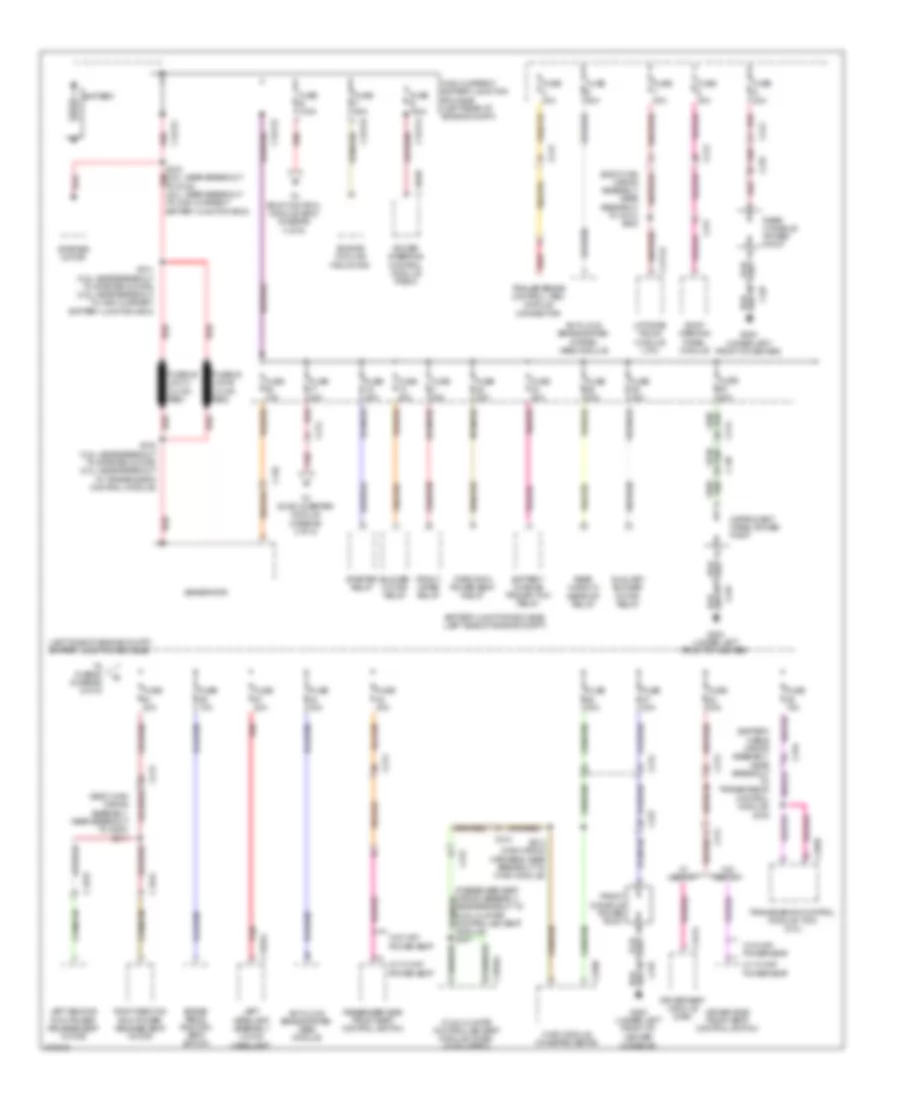
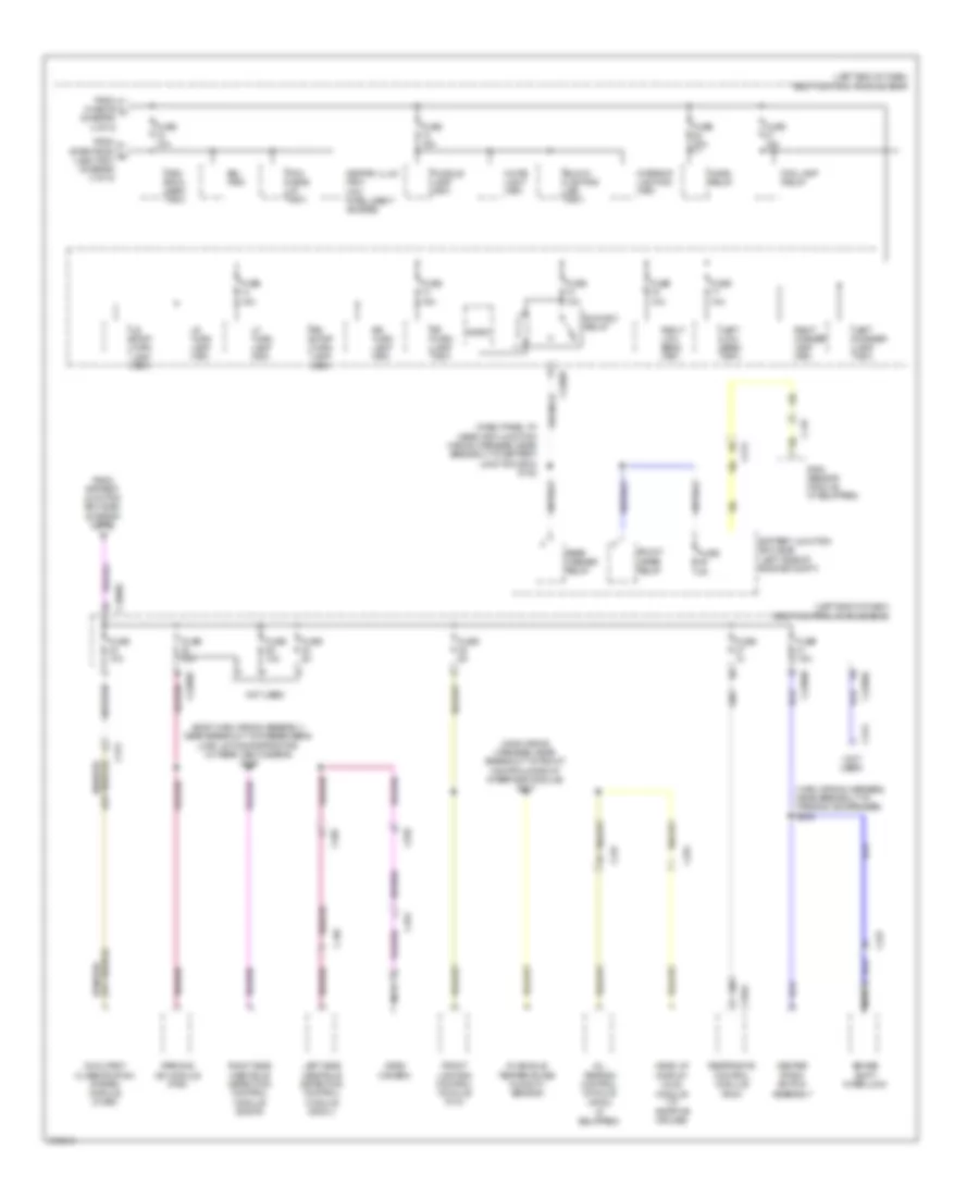
Электросхема блока предохранителей и реле (1 из 5) для Ford Explorer Limited 2012
Электросхема блока предохранителей и реле (1 из 5) для Ford Explorer Limited 2012 - Список элементов:
- (battery cable wiring assembly, near breakout to transmission control module) s105
- (body main wiring assembly, near breakout to c213) s300
- (body main wiring assembly, near breakout to g300) s311
- (left side of engine compt) battery junction box (bjb)
- Anti-lock brake system (abs) module
- Anti-lock brake system system (abs) module
- Auxiliary blower motor relay
- Battery
- Battery charge trailer tow relay
- Battery junction box (bjb) (left side of engine compt)
- Blower motor relay
- Brake pedal position (bpp) switch
- C1284a
- C139
- C1463b
- C1617a
- C1617b
- C1617c
- C1617d
- C210
- C212
- C213
- C228b
- C237
- C311
- C312
- C3133
- C3134
- C317
- C319
- C3265a
- C341a
- C4174a
- Driver seat module (dsm)
- Driver side front seat control switch
- Dual climate controlled seat module (dcsm) (if equipped)
- Engine cooling fan motor
- Front console power point
- Front wiper relay
- Fuse 10a
- Fuse 15a
- Fuse 20a
- Fuse 30a
- Fuse 40a
- Fuse 50a
- Fuse b 100a
- Fuse e 100a
- Fuse f 60a
- Fusible link a (10 ga- red)
- Fusible link b (10 ga- red)
- G200 (under left front of center console)
- G200 (under left front of center)
- Generator
- High current battery junction box (bjb) (left rear of engine compt)
- Hvac module (w/heated seats)
- Instrument panel power point
- Left headlamp assembly (w/ hid headlamp)
- Left second row power release seat motor
- Liftgate/ trunk module (ltm)
- Passenger side front seat control switch
- Power steering control module (pscm)
- Rear console power point
- Rear window defrost relay
- Red
- Right second row power release seat motor
- Roof opening panel module
- S100 (3.5l: near breakout to starter motor) (2.0l: near breakout to transmission control module)
- S101 (3.5l: near breakout to starter motor) (2.5l: near breakout to high current battery junction box)
- S102 (3.5l: near breakout to g100) (2.0l: near breakout to high current battery junction box)
- S213 (main wiring harness, near breakout to hvac module)
- S341
- Starter motor
- Starter relay
- Third row power seat relay
- To body control module (bcm) (diagram 3 of 5)
- To dc/ac inverter module (diagram 4 of 5)
- To fuse 60 (diagram 2 of 5)
- Trailer brake control (tbc) module connector
- Transmission control module (tcm) (2.0l)
- W/ 10-way power seat
- W/ 6-way power seat
- W/ memory
- W/o memory
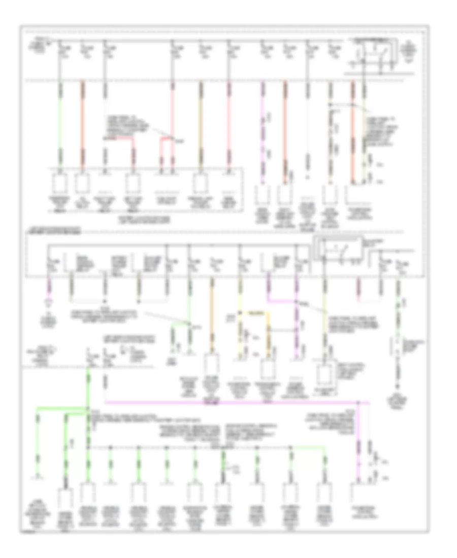
Электросхема блока предохранителей и реле (2 из 5) для Ford Explorer Limited 2012
Электросхема блока предохранителей и реле (2 из 5) для Ford Explorer Limited 2012 - Список элементов:
- (3.5l)
- (dash panel to headlamp junction wiring harness, near breakout to battery junction box)
- (dash panel to headlamp junction wiring harness, near breakout to battery junction box) s130
- (dash panel to headlamp junction wiring harness, near breakout to brake fluid level switch)
- (engine control sensor & fuel charge wiring assembly, near breakout to fuel injector 3) (3.5l) s154
- (engine control sensor & fuel charge wiring assembly, near breakout to variable camshaft timing 11 solenoid) (2.0l) s173
- (left side of engine compt) battery junction box (bjb)
- (not used)
- 2.0l
- 3.5l
- A/c clutch relay
- Anti-lock brake system (abs) module
- Auxiliary blower motor relay
- Battery charge trailer tow relay
- Battery junction box (bjb) (left side of engine compt)
- Blower motor relay
- Body control module (bcm) (left end of dash)
- C1285a
- C1381b
- C139
- C140
- C1463a
- C175b
- C175o
- C213
- C2280f
- C3053
- C935
- Cruise control module (ccm) (w/ adaptive cruise)
- Evap canister vent control solenoid
- Evaporative emission (evap) canister purge valve
- From fuse 61 b (diagram 1 of 5)
- From pcm power d relay (diagram 2 of 5)
- Fuel pump (fp) relay
- Fuse 10a
- Fuse 15a
- Fuse 20a
- Fuse 30a
- Fuse 5a
- Fuse 7.5a
- G301 (left rear quarter panel)
- Heated oxygen sensor (ho2s) 12 (2.0l)
- Heated oxygen sensor (ho2s) 12 (3.5l)
- Heated oxygen sensor (ho2s) 22 (3.5l)
- Left turn trailer tow relay
- Mass air flow/ intake air temperature (maf/iat) sensor (3.5l)
- Nca
- Parking lamp trailer tow relay
- Pcm power relay
- Power steering control module (pscm)
- Powertrain control module (pcm)
- Rear washer relay
- Rear window defrost relay
- Rear window wiper motor
- Red
- Reversing trailer tow relay
- Right headlamp assembly (w/ hid headlamps)
- Right turn trailer tow relay
- Run/start (fet)
- Run/start relay
- S115 (dash panel to headlamp junction wiring harness, near breakout to anti-lock brake system module)
- S119
- S123
- S125 (dash panel to headlamp junction wiring harness, near breakout to battery junction box)
- S129
- S132 (2.7l)
- Third row power point
- To fuse 33 (diagram 5 of 5)
- To fuse 67 (diagram 2 of 5)
- To fuse 68 (diagram 3 of 5)
- Transmission control module (tcm) (2.0l)
- Universal heated oxygen sensor (ho2s) 11
- Universal heated oxygen sensor (ho2s) 21 (3.5l)
- Variable camshaft timing 11 (vct11) solenoid
- Variable camshaft timing 12 (vct12) solenoid
- Variable camshaft timing 21 (vct21) solenoid (3.5l)
- Variable camshaft timing 22 (vct22) solenoid
- Wiring harness, near breakout to battery junction box)
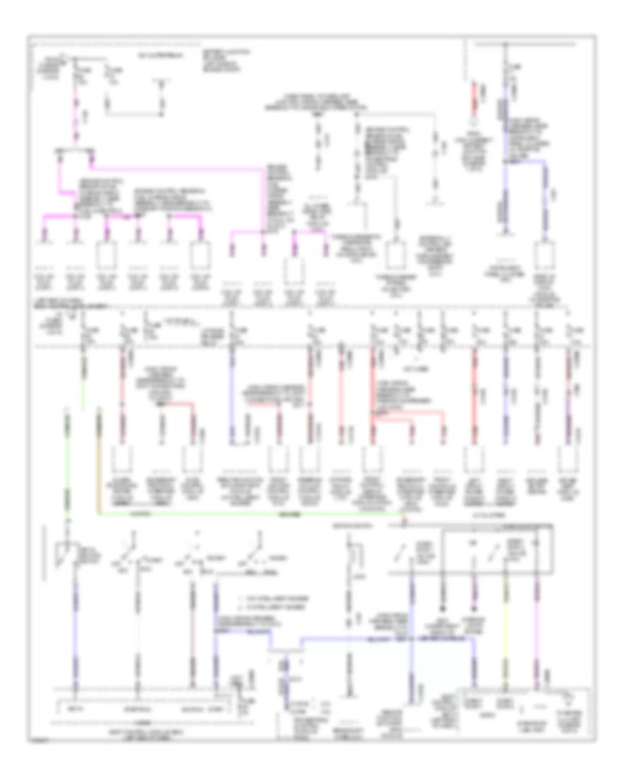
Электросхема блока предохранителей и реле (3 из 5) для Ford Explorer Limited 2012
Электросхема блока предохранителей и реле (3 из 5) для Ford Explorer Limited 2012 - Список элементов:
- (dash panel to headlamp junction wiring harness, near breakout to windshield wiper motor) s113
- (engine control sensor & fuel charge wiring assembly, near breakout to c140 powertrain control module) s172
- (engine control sensor & fuel charge wiring assembly, near breakout to coil on plug 2) s175
- (left end of dash) body control module (bcm)
- (main wiring harness, near breakout to c212) s201
- (main wiring harness, near breakout to instrument panel cluster) (w/ adaptive cruise) s204
- (main wiring harness, near breakout to joint connector 6 (hs-can)) (w/ sync) s212
- (main wiring harness, near breakout to joint connector 6 (hs-can)) s211
- (main wiring harness, near breakout to parking aid speaker) (w/o sync) s203
- (not used)
- 2.0l
- 3.5l
- A/c clutch relay
- Acc
- Acc/run
- Accessory protocol interface module (apim)
- Accessory protocol interface module (apim) (w/ sync)
- All wheel drive (awd) relay module (3.5l)
- Audio control module (acm)
- Battery junction box (bjb) (left side of engine compt)
- Body control module (bcm) (left end of dash)
- Brake shift interlock
- C1381b
- C139
- C140
- C175b
- C212
- C213
- C2153c
- C2280a
- C2280b
- C2280d
- C2280g
- C237
- C240a
- C2414a
- C291
- C300
- C3138
- C3139
- C341b
- C4174a
- Coil on plug (cop) 1
- Coil on plug (cop) 2
- Coil on plug (cop) 3
- Coil on plug (cop) 4
- Coil on plug (cop) 5
- Coil on plug (cop) 6
- Driver seat module (dsm)
- Externally controlled variable displacement compressor (evdc) (2.0l)
- From e fuse 69 (diagram 2 of 5)
- From high current battery junction box (bjb) (diagram 1 of 5)
- Front control/ display interface module (fcdim) (w/o sync)
- Front controls interface module (fcim)
- Front lighting control module (flm)
- Fuel injector 3) s155
- Fuse 10a
- Fuse 15a
- Fuse 20a
- Fuse 30a
- Fuse 5a
- Fuse 7.5a
- G201 (under right front of center console)
- Global positioning system module (gpsm)
- Head up display (hud) module (w/ adaptive cruise)
- Ignition switch
- Instrument panel cluster (ipc)
- Interior lights system
- Key in
- Key in ignition switch
- Keyless entry keypad
- Left front power window motor
- Liftgate release relay
- Liftgate/ trunk module (ltm)
- Lock
- Micro
- Nca
- Not used
- Off
- Powertrain control module (pcm)
- Red
- Remote function actuator (rfa) module
- Remote function actuator (rfa) module (w/ intelligent access)
- Right front power window motor
- Run
- Start
- Start/ stop 1
- Start/ stop 1 (active high)
- Start/ stop 2
- Start/ stop 2 (active low)
- Start/run
- Start/stop (led) (fet)
- Start/stop switch
- Steering column control module (sccm)
- To fuse 5 (diagram 4 of 5)
- To keypad illu (fet) (diagram 5 of 5)
- Turbocharger bypass valve(tcby) (2.0l)
- Turbocharger(tc) wastegate regulating valve solenoid (2.0l)
- W/ intelligent access
- W/ sync
- W/o intelligent access
- Xlt & limited
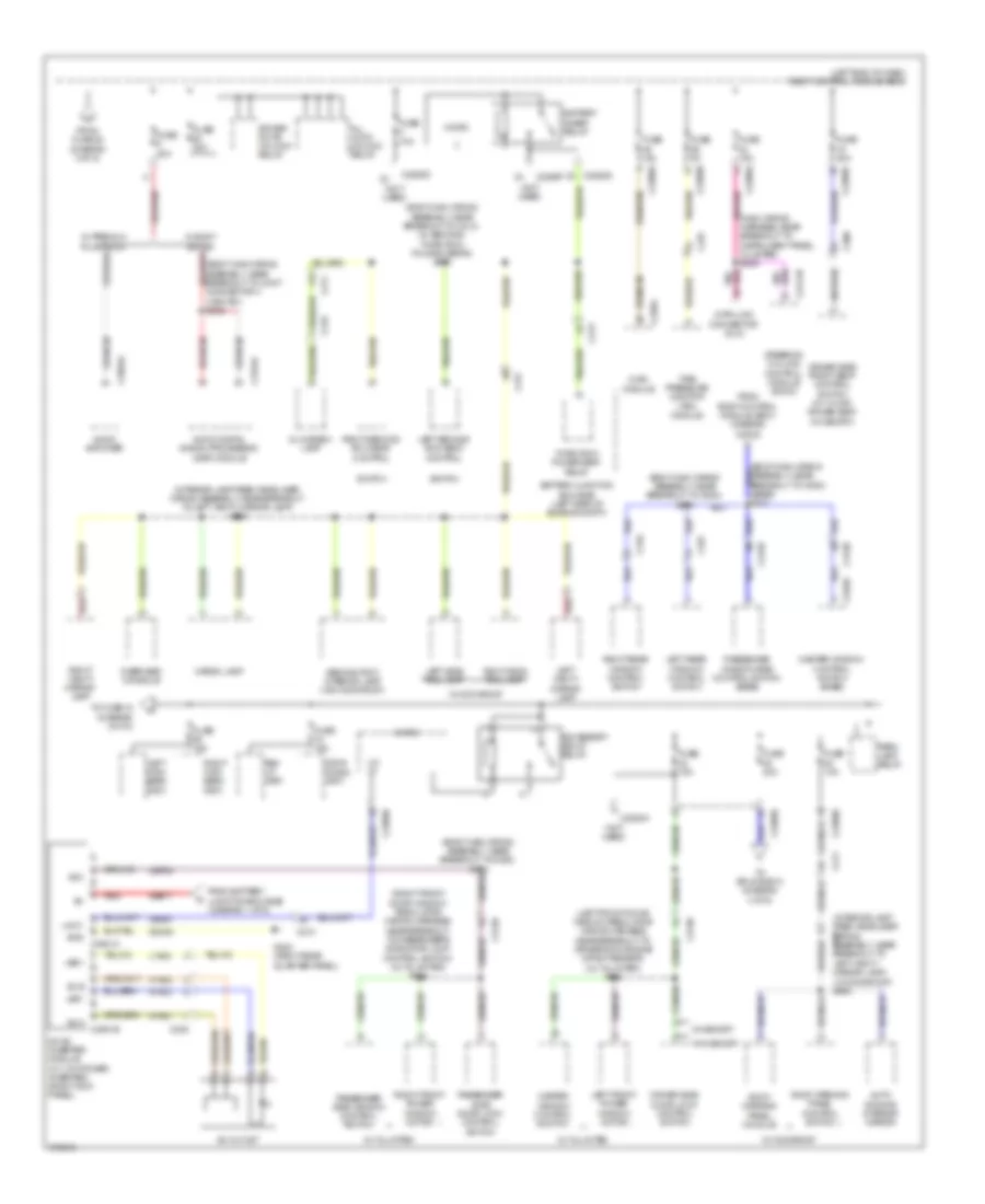
Электросхема блока предохранителей и реле (4 из 5) для Ford Explorer Limited 2012
Электросхема блока предохранителей и реле (4 из 5) для Ford Explorer Limited 2012 - Список элементов:
- (body main wiring assembly, near breakout to c213) (w/ second/ third row folding seats) s305
- (body main wiring assembly, near breakout to g300) s303
- (body main wiring assembly, near breakout to joint connector 4 (hs-can)) s332
- (interior lamp feed headliner c317 wiring assembly, near breakout to left vanity mirror lamp)
- (interior lamp feed headliner wiring assembly, near breakout to left vanity mirror lamp) s901
- (left end of dash) body control module (bcm)
- (left front door window regulator wiring harness, near breakout to driver's door side impact sensor) (xlt & limited) s500
- (main wiring harness, near breakout to instrument panel cluster) s205
- (not used)
- (right front door window regulator wiring harness, near breakout to passenger's side door lock control switch) (xlt & limited) s604
- (w/ moonroof) s900
- Ac outlet
- Ac-a c3501b
- Ac-b
- Acc
- Accessory delay relay
- All lock/ unlock relay
- Audio amplifier
- Audio digital signal processing (dsp) module
- Auto- dimming interior mirror
- Battery junction box (bjb) (left side of engine compt)
- Battery saver relay
- C210
- C211
- C213
- C219
- C2280a
- C2280b
- C2280d
- C2280f
- C228a
- C237
- C238
- C2414b
- C300
- C3138
- C3139
- C3154c
- C316
- C317
- C327
- C3504a
- C535b
- Cargo lamp
- Cbp32
- Data link connector (dlc)
- Dc/ac inverter module (w/ 110v power inverter) (right kick panel)
- Driver door unlock relay
- Driver side door lock control switch
- Driver side front seat control switch (w/ 10-way power seat w/ memory)
- From battery junction box (bjb) (diagram 1 of 5)
- From body control module (bcm) (diagram 4 of 5)
- From fuse 28 (diagram 3 of 5)
- Fuse 10a
- Fuse 15a
- Fuse 20a
- Fuse 30a
- Fuse 5a
- G302 (right rear quarter panel)
- Gd348
- Glove box lamp
- Gnd c3501a
- Hvac module
- Hya01
- Hya02
- Led+
- Led-
- Left front power window motor
- Left high beam (fet)
- Left rear window control switch
- Left second row seat control
- Left side rail lamp
- Left vanity mirror lamp
- Lin
- Lin 01
- Lya03
- Master window control switch
- Master window control switch (base)
- Micro
- Overhead console
- Park lamp relay
- Passenger side door lock control switch
- Passenger side window control switch
- Passenger window side control switch (base)
- Red
- Rev lp (fet)
- Right front power window motor
- Right high beam (fet)
- Right rear window control switch
- Right second row seat control
- Right side rail lamp
- Right vanity mirror lamp
- Roof opening panel control switch
- Roof opening panel module
- Rya03
- Sbb17
- Second row interior lamp (w/o moonroof)
- Steering column control module (sccm)
- Stop/ chmsl (fet)
- Switch
- Third row power seat relay
- Tire pressure monitor (tpm) module
- To fuse 18 (diagram 5 of 5)
- To splice s310 (diagram 4 of 5)
- Vdn01
- W/ memory
- W/ moonroof
- W/ premium plus audio
- W/ sony sound
- W/o memory
- Xlt & limited
Электросхема блока предохранителей и реле (5 из 5) для Ford Explorer Limited 2012
Электросхема блока предохранителей и реле (5 из 5) для Ford Explorer Limited 2012 - Список элементов:
- (body main wiring assembly, near breakout to passenger's load limiting retractor) (w/ rear view camera) s328
- (dash panel to headlamp junction wiring harness, near breakout to battery junction box) s122
- (if equipped)
- (left end of dash) body control module (bcm)
- (main wiring harness, near breakout to front control/display interface module) s217
- (main wiring harness, near breakout to parking aid speaker) s202
- (not used)
- 3rd row seat (fet)
- All terrain control module (atcm)
- Battery junction box (bjb) (left side of engine compt)
- Block lighting led (fet)
- Brake shift interlock
- Bsi (fet)
- C213
- C2280b
- C2280d
- C2280e
- C2280f
- C237
- C291
- C310a
- C312
- C313
- C317
- C405
- C465
- C494
- C935
- Center stack switch assembly
- Fog lamp relay
- From battery junction box (bjb) (diagram 2 of 5)
- From fuse 39 k (diagram 4 of 5)
- From start/stop h (led) (fet) (diagram 3 of 5)
- Front lighting control module (flm)
- Front wiper relay
- Fuse
- Fuse 10a
- Fuse 15a
- Fuse 20a
- Fuse 5a
- Fuse 7.5a
- Head up display (hud) module (w/ adaptive cruise)
- Horn relay
- In-vehicle temperature/ humidity sensor
- Interior lighting (fet)
- Keypad illum (fet) (w/o intelligent access)
- Left corner lamp (fet)
- Left low beam (fet)
- Left side obstacle detection control module (sod-l)
- Lf turn lamp (fet)
- Lr stop/ turn lamp (fet)
- Lr turn lamp (fet)
- Micro
- Nca
- Not used
- Occupant classification system module (ocsm)
- Parking aid module (pam)
- Pcm wake up (fet)
- Puddle lamp (fet)
- Rain sensor module (if equipped)
- Rear washer relay
- Restraints control module (rcm)
- Rf turn lamp (fet)
- Right corner lamp (fet)
- Right low beam (fet)
- Right side obstacle detection control module (sod-r)
- Rr stop/ turn lamp (fet)
- Rr turn lamp (fet)
- Run/acc relay
- Video camera
- White light (fet)

 Čeština
 Dansk
Dansk Deutsch
 Ελληνικά
 English
 Español
 Suomi
Suomi Français
 Français
 עברית
עברית Hrvatski
 Magyar
 Italiano
 日本語
日本語 한국어
한국어 Nederlands
 Polski
 Português
 Português
 Română
 Русский
 Slovenčina
 Slovenščina
 Svenska
 Türkçe
 中文 (中国)