ENGINE PERFORMANCE
1.6L TURBO
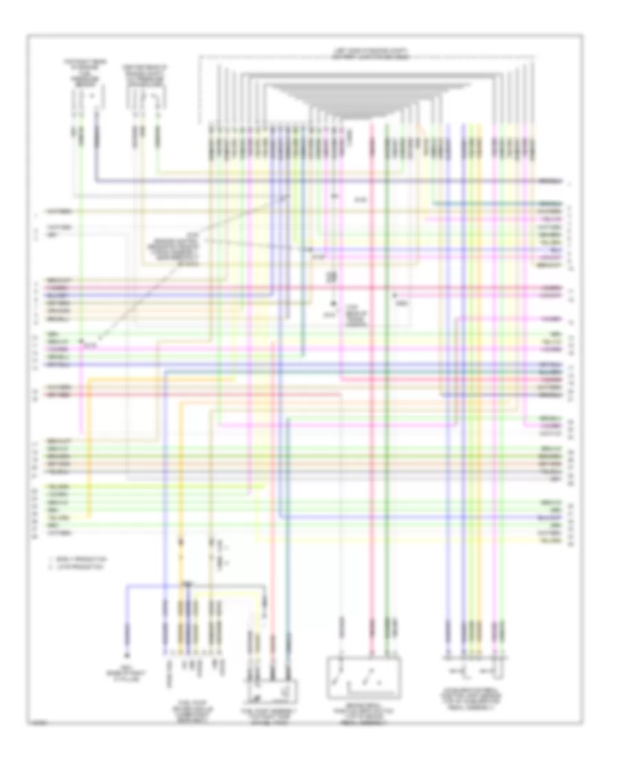
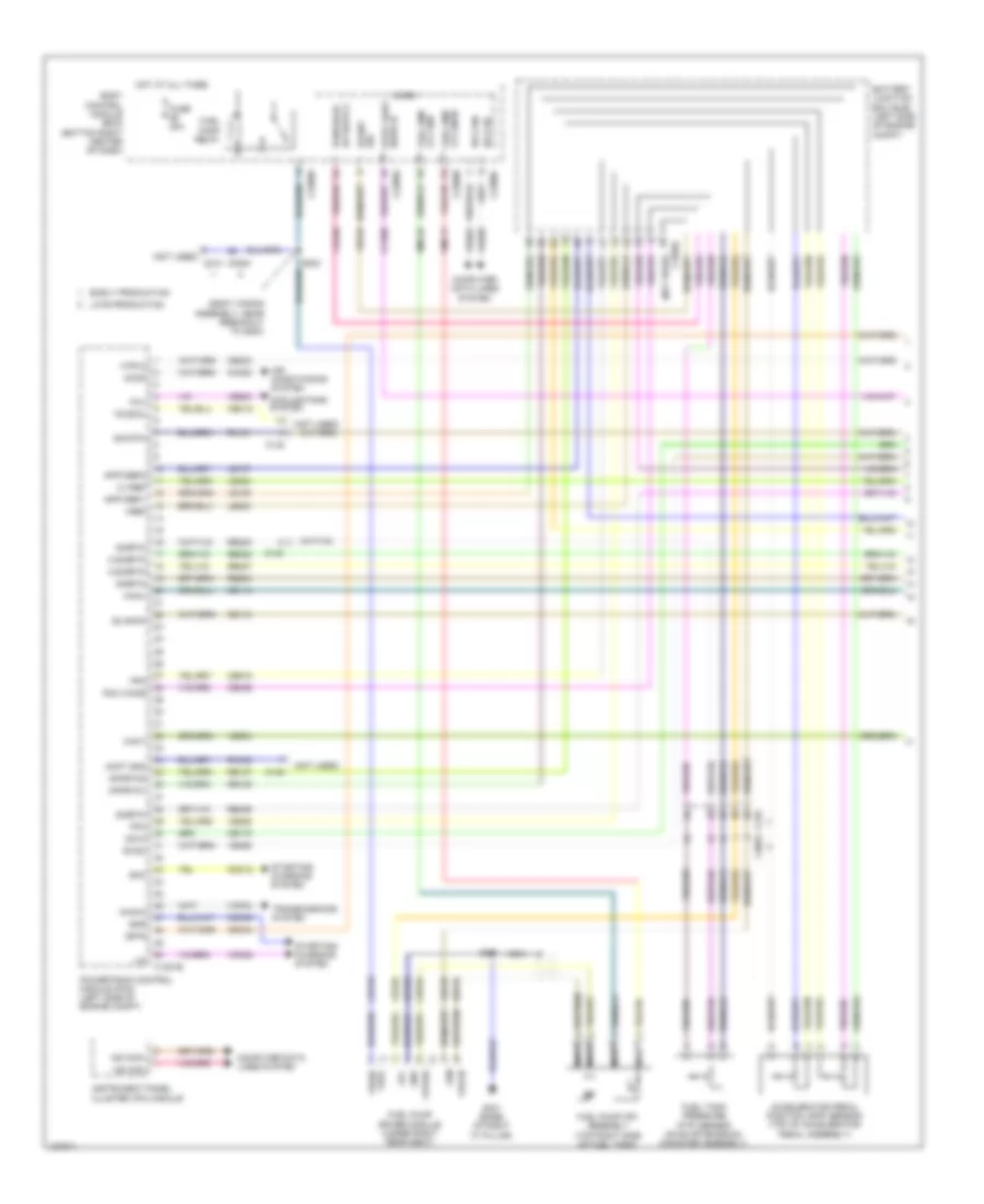
1.6L Turbo, Engine Performance Wiring Diagram (1 of 6) for Ford Escape S 2014

List of elements for 1.6L Turbo, Engine Performance Wiring Diagram (1 of 6) for Ford Escape S 2014:
- (not used)
- Accr
- Active grille shutter (behind right end of front grille)
- Air conditioning system
- Apprtn1
- Apprtn2
- Appvref1
- Appvref2
- Awdm
- Battery junction box (bjb) (left side of engine compt)
- C1035c
- C140
- C1551b
- C210
- C212
- C3053
- Cact
- Canv
- Cbb38
- Cdc12
- Cdv2
- Ce113
- Ce114
- Ce172
- Ce436
- Ch109
- Computer data lines system
- Cooling fans system
- Early production
- Evapcp
- Evaporative emission (evap) canister vent valve (under right rear of vehicle)
- Evdc
- Fcv
- Fpc
- Fpm
- Fuse 10a
- Fuse 15a
- Fuse 30a
- Fuse 5a
- Hot at all times
- Hot in start or run
- Htr12
- Instrument panel cluster (ipc) module
- Isp-r
- Late production
- Le136
- Le137
- Le230
- Lh108
- Lin
- Ms can+
- Ms can-
- Nca
- Pcm power relay
- Pcm wake
- Power distribution system
- Powertrain control module (pcm) (left side of engine compt)
- Re136
- Re137
- Re238
- Re242
- Re731
- Re804
- Ret42
- Rh107
- Sigrtn
- Smc
- Smr
- Sst gnd
- Sst+
- Sst-
- Starting/charging system
- Status
- Transmission control switch (base of shift lever assembly)
- Transmissions system
- Vcf34
- Vdc46
- Ve203
- Ve225
- Ve462
- Ve518
- Ve805
- Vpwr
- Vref
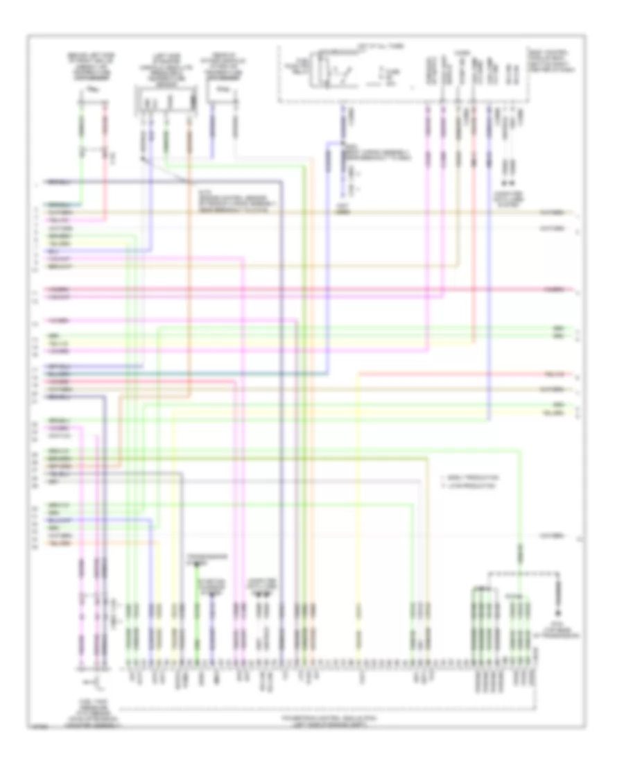
1.6L Turbo, Engine Performance Wiring Diagram (2 of 6) for Ford Escape S 2014
List of elements for 1.6L Turbo, Engine Performance Wiring Diagram (2 of 6) for Ford Escape S 2014:
- (center rear of engine compt) a/c pressure transducer
- (left side of engine compt) battery junction box (bjb)
- (top rear of trans- mission)
- (top right rear of engine) fuel pressure sensor
- Accelerator pedal position (app) sensor (top of accelerator pedal assembly)
- Brake pedal position (bpp) switch (top of brake pedal assembly)
- C1035c
- C210
- C3050
- Cbp56
- Ce515
- Early production
- Fpc
- Fpm
- Fppwr
- Fprtn
- Fuel pump assembly (top right side of fuel tank)
- Fuel pump driver module (under right rear seat)
- G104
- G301 (base of right "c" pillar)
- Gd152
- Gnd
- Late production
- Nca
- Re515
- S125
- S129
- S179
- S180 (engine control sensor extension wiring assembly, near breakout to g104)
- S250
- S301
- Ve225
- Ve518
- Vpwr fuel
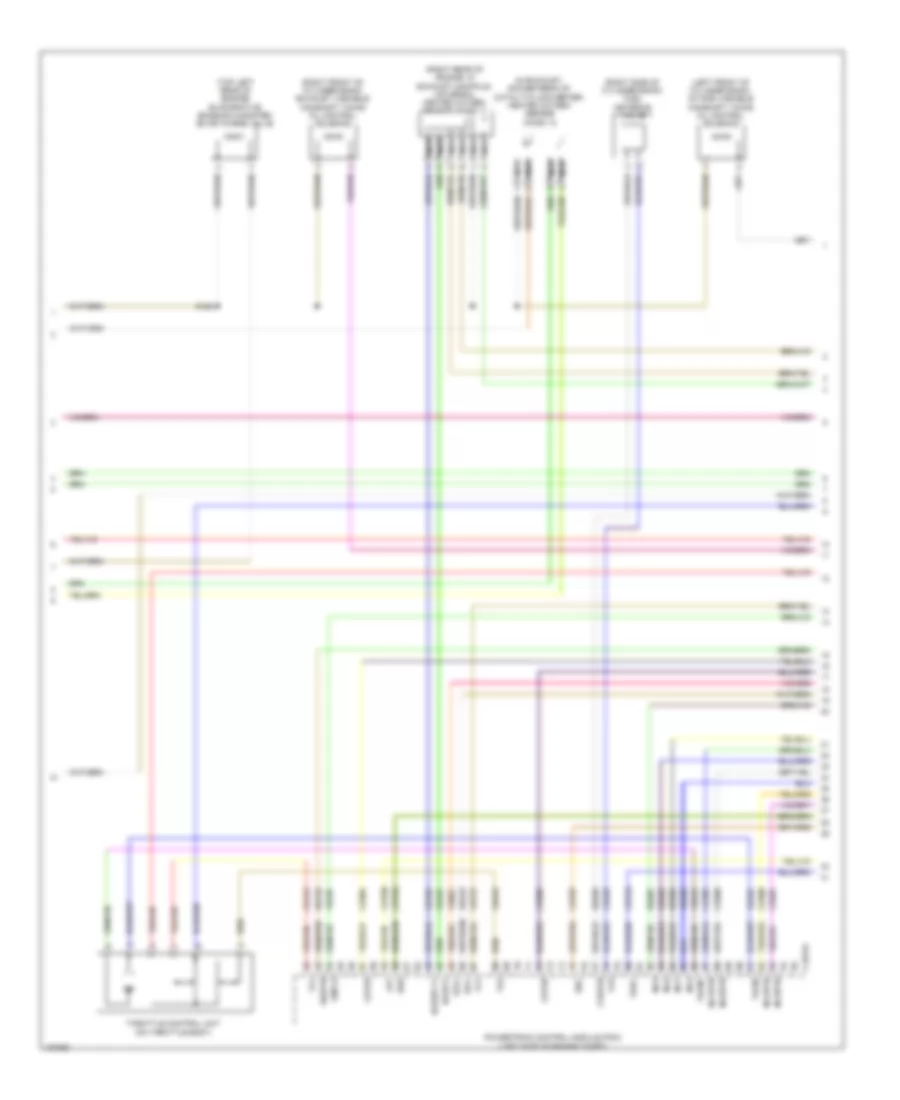
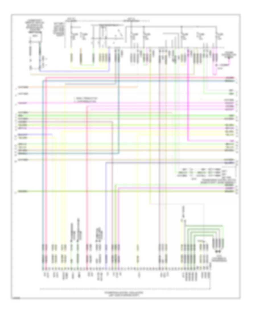
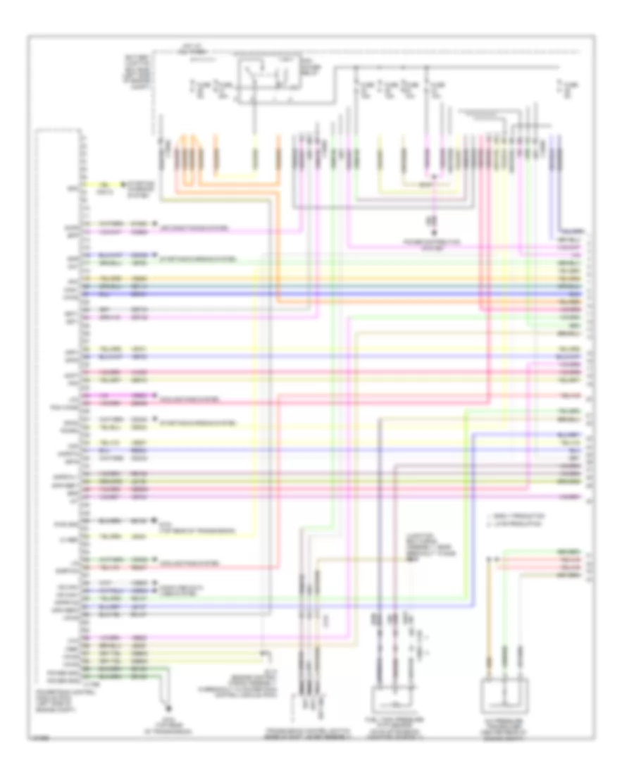
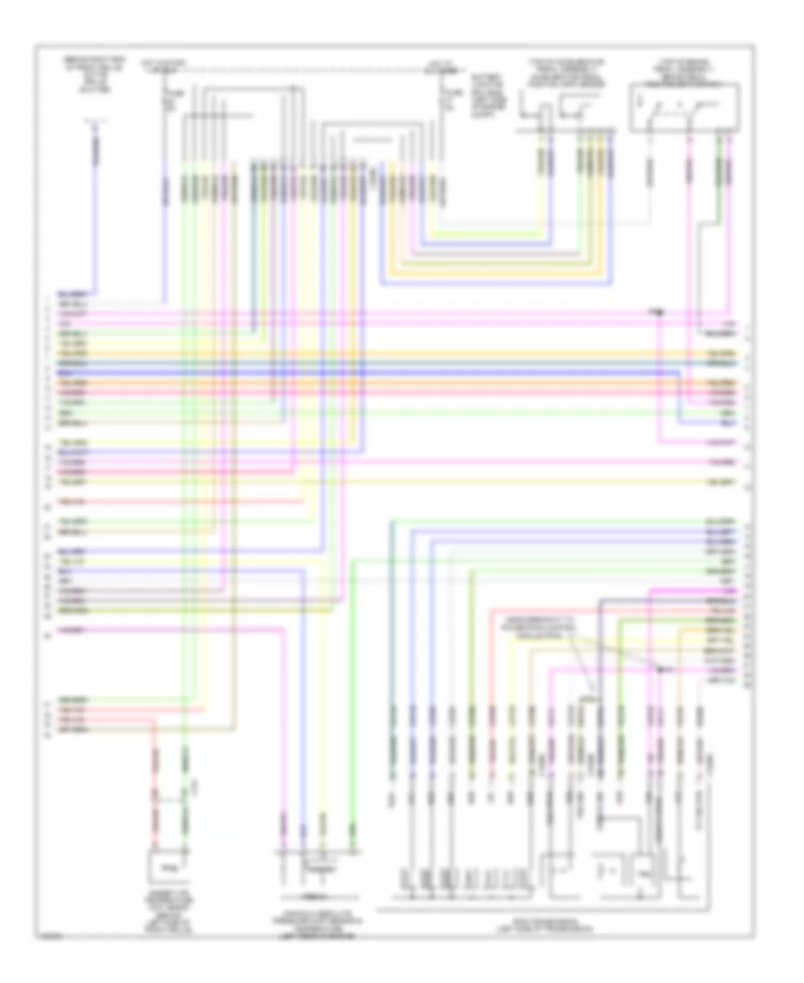
1.6L Turbo, Engine Performance Wiring Diagram (3 of 6) for Ford Escape S 2014
List of elements for 1.6L Turbo, Engine Performance Wiring Diagram (3 of 6) for Ford Escape S 2014:
- (behind left side of front grille) ambient air temperature (aat) sensor
- (left side of engine) manifold absolute pressure & temperature sensor
- (not used)
- (rear of intake manifold) intake air temperature (iat) sensor
- Aat
- Acpt
- App1
- App2
- Awdc
- Body control module (bcm) (bottom right center of dash)
- Bpp
- Bps
- C134
- C1551b
- C210
- C2280a
- C2280b
- C2280c
- C2280e
- C3053
- Cbb32
- Ccb08
- Cdc12
- Cdv1
- Ce171
- Ce302
- Ce436
- Ces09
- Cet34
- Cet42
- Cet43
- Computer data lines system
- Early production
- Event sig
- Flp
- Ftp
- Fuel pump (fp) relay
- Fuel pump lvl gnd
- Fuel tank pressure (ftp) sensor (on evap emission canister assembly)
- Fuse 20a
- G104 (top rear of transmission)
- Gd120
- Gnd
- Ho2s12
- Hot at all times
- Hs can+
- Hs can-
- Iat
- Late production
- Lvl sens fuel pump
- Micro
- Near breakout to g200)
- Pcmrc
- Powertrain control module (pcm) (left side of engine compt)
- Pres
- Pwrgnd
- Rmc32
- S125
- S131
- S178 (engine control sensor extension wiring assembly, near breakout to c1019)
- Smcs
- Sst+
- Sst-
- Starting/ charging system
- Switch stop light
- Tcbp
- Tcs
- Temp
- Transmissions system
- Vcc
- Vcf35
- Vdb04
- Vdb05
- Ve518
- Ve701
- Ve702
- Ve731
- Ve761
- Ve804
- Ve805
- Ve922
- Vh407
- Vh442
- Vmc11
- Vpwr
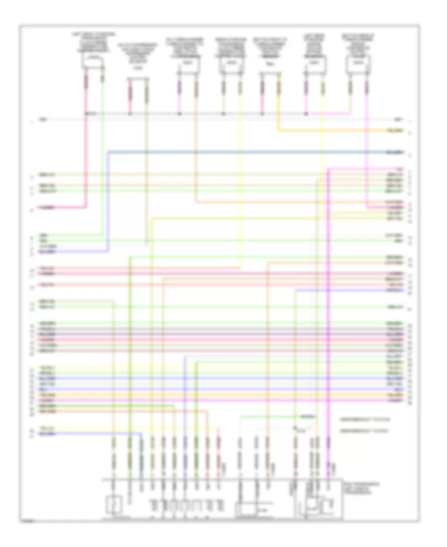
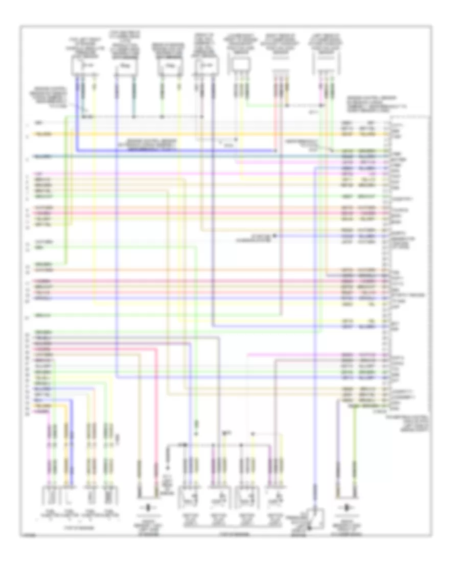
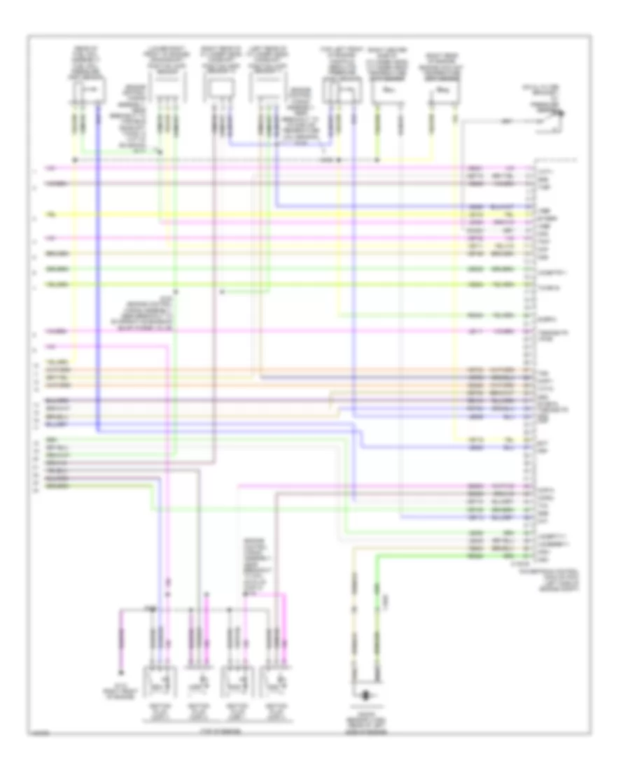
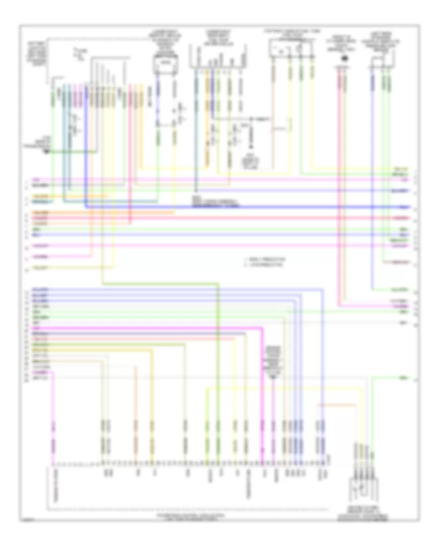
1.6L Turbo, Engine Performance Wiring Diagram (4 of 6) for Ford Escape S 2014
List of elements for 1.6L Turbo, Engine Performance Wiring Diagram (4 of 6) for Ford Escape S 2014:
- (in exhaust, downstream of catalytic converter) heated oxygen sensor (ho2s) 12
- (left front of cylinder bank) intake variable camshaft timing oil control solenoid
- (right front of cylinder bank) exhaust variable camshaft timing oil control solenoid
- (right rear of engine, in exhaust manifold) universal heated oxygen sensor (ho2s) 11
- (right side of cylinder bank) fuel metering valve
- (top left rear of engine) evaporative emission canister (evap) purge valve
- C1551e
- Ce205
- Ce206
- Ce207
- Ce208
- Ce256
- Ce304
- Ce305
- Ce412
- Cet05
- Cet07
- Cet09
- Cet25
- Cmp12
- Cop2d
- Cop3b
- Fvr
- Fvrrtn
- Inj1
- Inj1rtn
- Inj2
- Inj2rtn
- Inj3
- Inj3rtn
- Inj4
- Inj4rtn
- Ks1+
- Ks1-
- Le428
- Le448
- Le452
- Lpc
- Nca
- Powertrain control module (pcm) (left side of engine compt)
- Re135
- Re205
- Re206
- Re207
- Re208
- Re256
- Re323
- S128
- Sigrtn
- Ssa
- Ssc
- Tacm+
- Tacm-
- Tft
- Throttle control unit (on throttle body)
- Tp1
- Tp2
- Tspc
- Uo2s11
- Uo2spc11
- Ve707
- Ve801
- Ve818
- Ve819
- Vet27
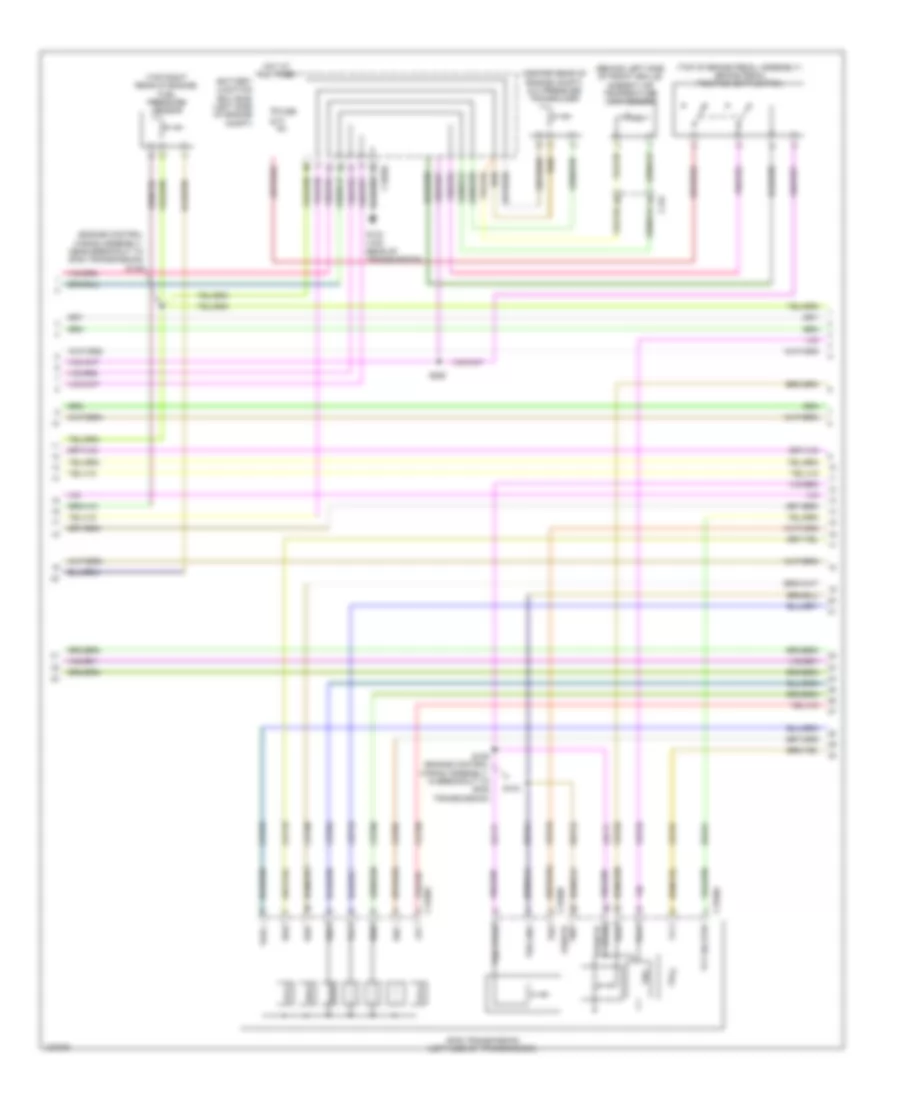
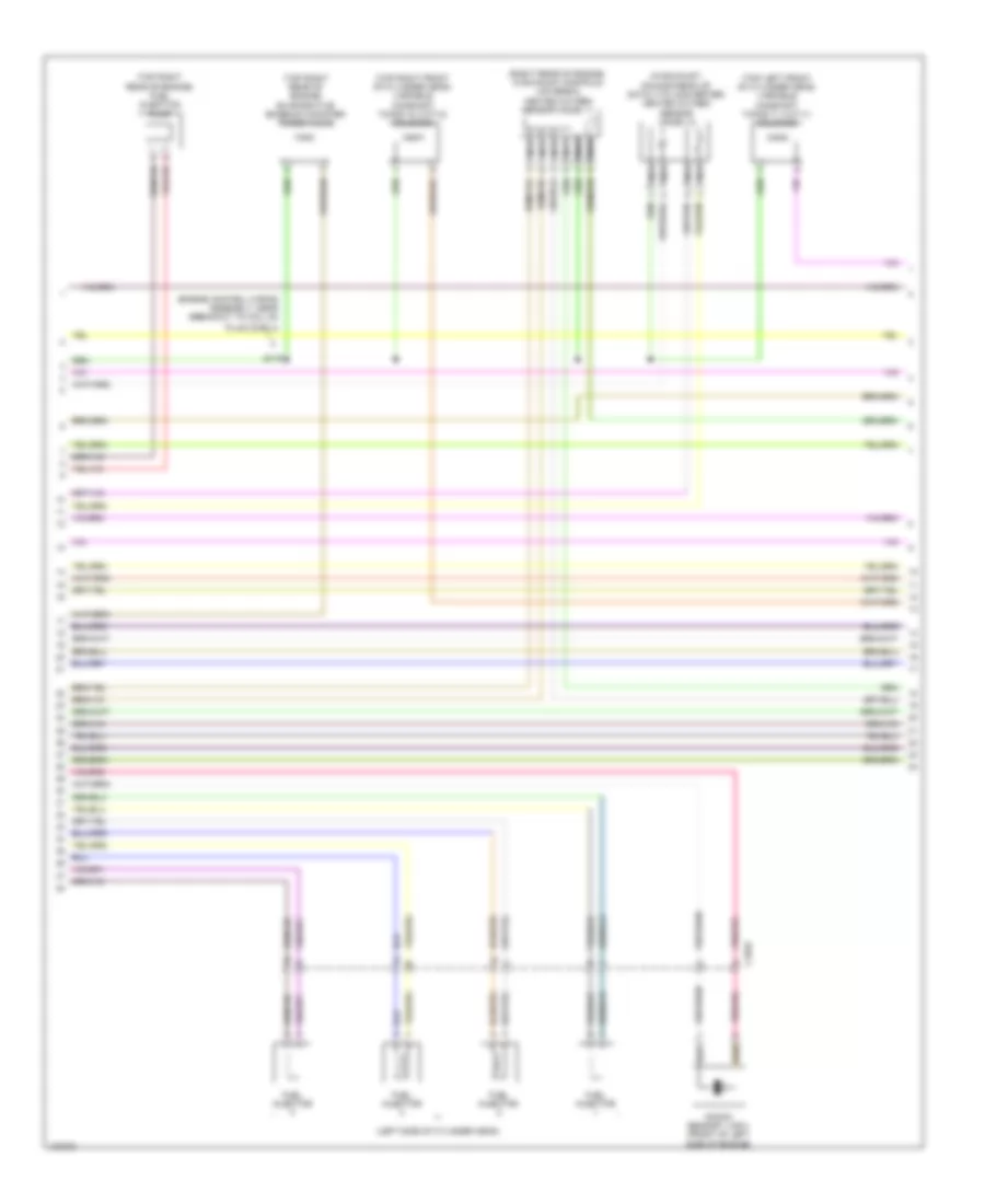
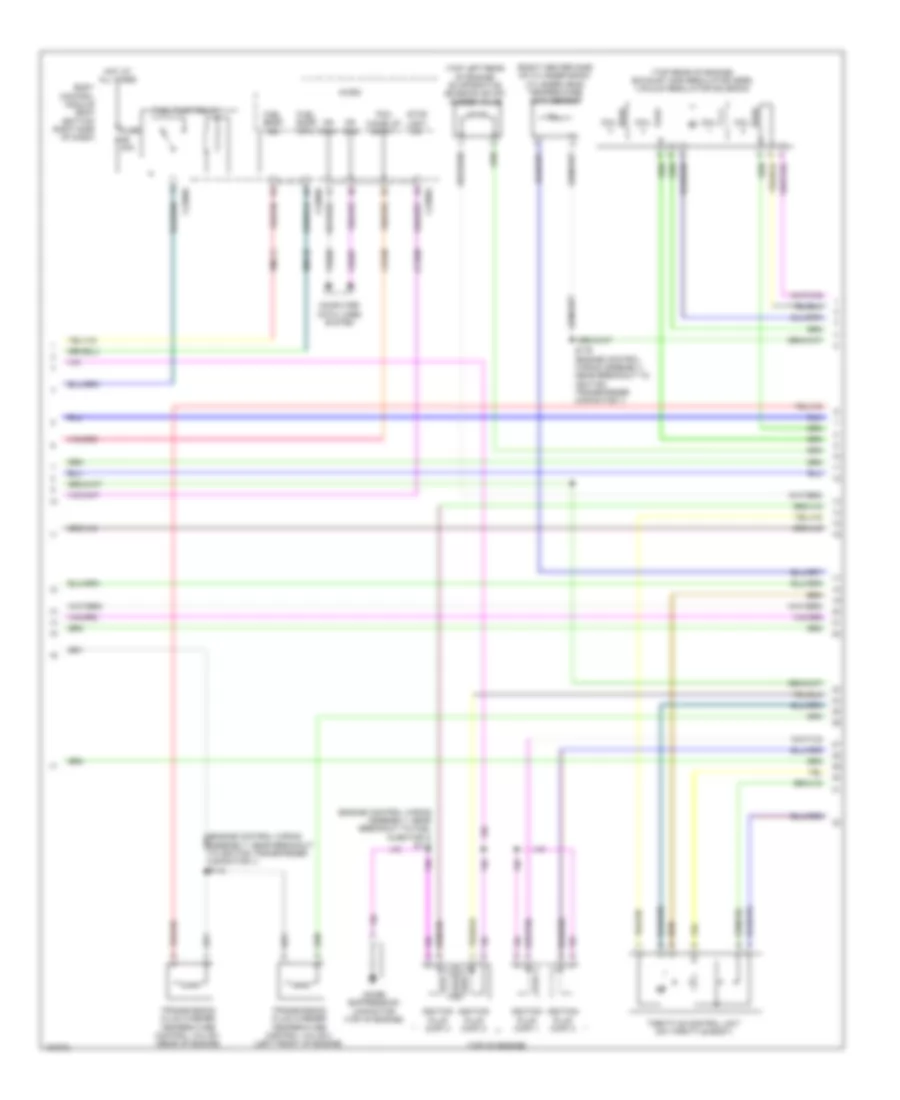
1.6L Turbo, Engine Performance Wiring Diagram (5 of 6) for Ford Escape S 2014
List of elements for 1.6L Turbo, Engine Performance Wiring Diagram (5 of 6) for Ford Escape S 2014:
- (bottom front of turbocharger) wastegate position sensor
- (bottom rear of turbocharger) engine wastegate control valve
- (left front of engine) transmission fluid warmer temperature control valve 2
- (left rear of engine) engine cooling bypass solenoid
- (near breakout to c1019)
- (near breakout to g104)
- (on a/c compressor) air conditioning compressor control solenoid
- (on turbocharger) turbocharger (tc) wastegate regulating valve solenoid
- (rear of engine) transmission fluid warmer temperature control valve 1
- 6f35 transmission (left side of transmission)
- C1520a
- C1520b
- Cet05
- Cet06
- Cet07
- Cet08
- Cet09
- Cet10
- Cet18
- Cet25
- Let57
- Lpc
- Oss
- Oss/tr gnd
- Oss/tr vpwr
- Ret24
- Ret26
- Ret33
- Ret35
- S110
- S130
- S132
- Ssa
- Ssb
- Ssc
- Ssd
- Sse
- Tcc
- Tft
- Tft sig rtn
- Tr-p
- Trs
- Tspc
- Tss
- Tss gnd
- Tss vpwr
- Vet27
- Vet32
- Vet33
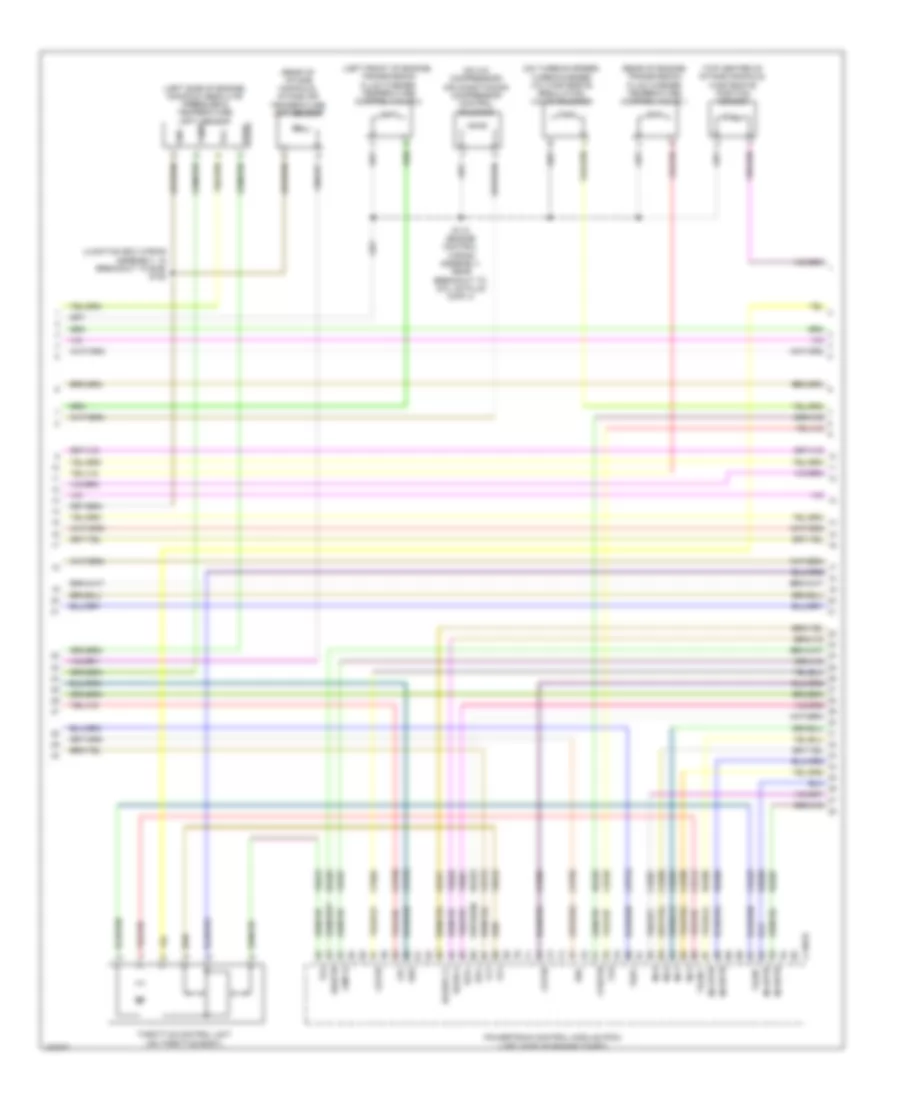
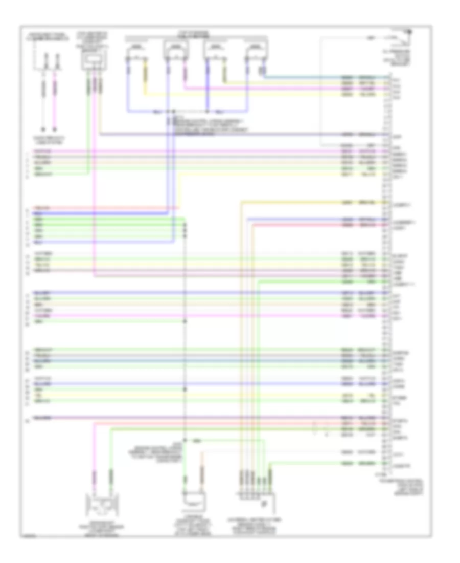
1.6L Turbo, Engine Performance Wiring Diagram (6 of 6) for Ford Escape S 2014
List of elements for 1.6L Turbo, Engine Performance Wiring Diagram (6 of 6) for Ford Escape S 2014:
- (engine control sensor extension wiring assembly, near breakout to c1026)
- (engine control sensor extension wiring assembly, near breakout to g111)
- (engine control sensor extension wiring assembly, near breakout to knock sensor 2 (ks2))
- (front of fuel rail assembly) fuel rail pressure (frp) sensor
- (left rear of cylinder bank) intake camshaft position (cmp) sensor
- (lower right front of engine) crankshaft position (ckp) sensor
- (near breakout to c1019) s127
- (rear of engine) engine coolant temperature (ect) sensor
- (right rear of cylinder bank) exhaust camshaft position (cmp) sensor
- (top center of cylinder head) (late production) cylinder head temperature (cht) sensor
- (top left front of engine) manifold absolute pressure (map) sensor
- (top of engine)
- C1026
- C1551e
- Ce148
- Ce149
- Ce167
- Ce178
- Ce303
- Ce306
- Ce426
- Ce501
- Ce508
- Ce908
- Cet06
- Cet08
- Cet10
- Cet18
- Cht
- Ckp
- Cmp11
- Cop1a
- Cop4c
- Ecbv
- Ecrv
- Ect
- Ectref
- Etcrtn tss/oss/
- Frp
- Fuel injector
- G111 (left rear of engine)
- Generator
- Ignition plug (cop) 1
- Ignition plug (cop) 2
- Ignition plug (cop) 3
- Ignition plug (cop) 4
- Knock sensor 1 (ks1) (left side of engine)
- Knock sensor 2 (ks2) (front of cylinder bank)
- Ks2+
- Ks2-
- Le135
- Le143
- Le451
- Let57
- Map
- Oil pressure switch (left side of engine)
- Ops
- Oss
- Powertrain control module (pcm) (left side of engine compt)
- Re324
- Re329
- Re427
- Ret24
- Ret26
- S111
- S122
- S123
- S124
- S126
- Sigrtn
- Ssb
- Ssd
- Sse
- Starting/ charging system
- Tcby
- Tcc
- Tcwrvs
- Tp gnd
- Tr-p
- Tss
- Tss/oss/ tp vpwr
- Uo2sgref11
- Uo2shtr11
- Uo2spct11
- Vct11
- Vct12
- Vdc46
- Ve706
- Ve711
- Ve712
- Ve716
- Ve727
- Ve802
- Ve803
- Ve826
- Ve827
- Vet32
- Vet33
- Vref
2.0L TURBO
2.0L Turbo, Engine Performance Wiring Diagram (1 of 6) for Ford Escape S 2014
List of elements for 2.0L Turbo, Engine Performance Wiring Diagram (1 of 6) for Ford Escape S 2014:
- (body wiring assembly, near breakout to g200)
- (not used)
- (not used) c210
- Accelerator pedal position (app) sensor (top of accelerator pedal assembly)
- Accr
- Acpt gnd
- Air conditioning system
- Apprtn1
- Apprtn2
- Appvref1
- Appvref2
- Awd-m
- Battery junction box (bjb) (left side of engine compt)
- Body control module (bcm) (bottom right center of dash)
- C-sigrtn
- C-vref
- C1035c
- C1381b
- C140
- C210
- C2280a
- C2280b
- C2280c
- C2280e
- C3053
- Cact
- Canv
- Cbp56
- Ccb08
- Cdc12
- Cdc34
- Cdc35
- Cdv2
- Ce113
- Ce114
- Ce172
- Ce233
- Ce436
- Ce515
- Cec12
- Ch302
- Computer data lines system
- Cooling fans system
- Early production
- Evapcp
- Evdc
- Event sig
- Fc(gcc)
- Fcv
- Fpc
- Fpm
- Fppwr
- Fprtn
- Fuel pmp lvl gnd
- Fuel pump (fp) assembly (top right side of fuel tank)
- Fuel pump driver module (under right rear seat)
- Fuel pump relay
- Fuel tank pressure (ftp) sensor (on evap emission canister assembly)
- Fuel vpwr
- Fuse 20a
- G301 (base of right "c" pillar)
- Gd152
- Gnd
- Hot at all times
- Hs can+
- Hs can-
- Htr12
- Instrument panel cluster (ipc) module
- Isp-r
- Late production
- Le136
- Le137
- Le230
- Le424
- Lin
- Lvl snsr fuel pmp
- Micro
- Ms can+
- Ms can-
- Nca
- Pcm wake
- Powertrain control module (pcm) (left side of engine compt)
- Re136
- Re137
- Re230
- Re238
- Re406
- Re407
- Re515
- Re804
- Rh433
- Rmc32
- Rx101
- S203
- S301
- Sig rtn
- Sigrtn
- Smc
- Smr
- Starting/ charging system
- Stop light switch
- Transmissions system
- Vcf34
- Vdb04
- Vdb05
- Vdn08
- Ve203
- Ve225
- Ve462
- Ve518
- Ve804
- Vmc11
- Vref
2.0L Turbo, Engine Performance Wiring Diagram (2 of 6) for Ford Escape S 2014
List of elements for 2.0L Turbo, Engine Performance Wiring Diagram (2 of 6) for Ford Escape S 2014:
- (not used)
- (under right rear of vehicle) evaporative emission (evap) canister vent valve
- Aat
- Acpt
- App1
- App2
- Awd-c
- Battery junction box (bjb) (left side of engine compt)
- Bpp
- Bps
- C1035c
- C1381b
- C140
- C210
- C212
- C3053
- Cbb08
- Ccb08
- Cdc54
- Cdv1
- Ce171
- Ce302
- Ces09
- Cet34
- Cet42
- Cet43
- Early production
- Ect+
- Flp
- Ftp
- Fuse 10a
- Fuse 15a
- Fuse 30a
- Fuse 5a
- G104 (top rear of transmission)
- Gd120
- Ho2s12
- Hot at all times
- Hot in start or run
- Hs can+
- Hs can-
- Iat
- Late production
- Nca
- Pcm power relay
- Pcmrc
- Power distribution system
- Powertrain control module (pcm) (left side of engine compt)
- Pwrgnd
- S103
- S147
- Smcs
- Sst gnd
- Sst+
- Sst-
- System data lines computer
- System starting/charging
- System transmissions
- Tcbp
- Tcs
- Transmission control switch (base of shift lever assembly)
- Vcf35
- Vcf36
- Vdb04
- Vdb05
- Ve701
- Ve702
- Ve727
- Ve731
- Ve740
- Ve750
- Ve805
- Ve922
- Vh443
- Vpwr
2.0L Turbo, Engine Performance Wiring Diagram (3 of 6) for Ford Escape S 2014
List of elements for 2.0L Turbo, Engine Performance Wiring Diagram (3 of 6) for Ford Escape S 2014:
- (behind left side of front grille) ambient air temperature (aat) sensor
- (center rear of engine compt) a/c pressure transducer
- (engine control wiring assembly, near breakout to 6f35 transmission) s105
- (top of brake pedal assembly) brake pedal position (bpp) switch
- (top right rear of engine) fuel pressure sensor
- 6f35 transmission (left side of transmission)
- Battery junction box (bjb) (left side of engine compt)
- C1035c
- C134
- C1520a
- C1520b
- Cet05
- Cet06
- Cet07
- Cet08
- Cet09
- Cet10
- Cet18
- Cet25
- Fuse 5a
- G104 (top rear of transmission)
- Gnd oss/tr
- Hot at all times
- Le111
- Lpc
- Oss
- Re454
- Ret24
- S104
- S106 (engine control wiring assembly, in breakout to 6f35 transmission)
- S250
- Ssa
- Ssb
- Ssc
- Ssd
- Sse
- Tcc
- Tft
- Tft sig rtn
- Tr-p
- Trs
- Tspc
- Tss
- Tss gnd
- Tss vpwr
- Vet26
- Vet27
- Vet32
- Vet33
- Vpwr oss/tr
2.0L Turbo, Engine Performance Wiring Diagram (4 of 6) for Ford Escape S 2014
List of elements for 2.0L Turbo, Engine Performance Wiring Diagram (4 of 6) for Ford Escape S 2014:
- (junction box wiring assembly, in breakout to bjb) s182
- (left front of engine) transmission fluid warmer temperature control valve 2
- (left side of engine) manifold absolute pressure & temperature (apt) sensor
- (on a/c compressor) air conditioning compressor control solenoid
- (on turbocharger) turbocharger (tc) wastegate regulating valve solenoid
- (rear of engine) transmission fluid warmer temperature control valve 1
- (rear of intake manifold) intake air temperature (iat) sensor
- (top center of intake manifold) wastegate position sensor
- C1381e
- Ce205
- Ce206
- Ce207
- Ce208
- Ce226
- Ce304
- Ce305
- Ce412
- Ce426
- Cet05
- Cet07
- Cet09
- Cet25
- Cmp12
- Cop2d
- Cop3b
- Fvr
- Fvrrtn
- Gnd
- Inj1
- Inj1rtn
- Inj2
- Inj2rtn
- Inj3
- Inj3rtn
- Inj4
- Inj4rtn
- Ks1+
- Ks1-
- Le451
- Lpc
- Powertrain control module (pcm) (left side of engine compt)
- Pres
- Re205
- Re206
- Re207
- Re208
- Re226
- Re323
- Re405
- S118 (engine control wiring assembly, near breakout to coil on plug (cop) 4)
- Sigrtn
- Ssa
- Ssc
- Tacm +
- Tacm -
- Temp
- Tft
- Throttle control unit (on throttle body)
- Tp1
- Tp2
- Tspc
- Uo2s11
- Uo2spc11
- Vcc
- Ve707
- Ve801
- Ve818
- Ve819
- Ve826
- Vet27
2.0L Turbo, Engine Performance Wiring Diagram (5 of 6) for Ford Escape S 2014
List of elements for 2.0L Turbo, Engine Performance Wiring Diagram (5 of 6) for Ford Escape S 2014:
- (engine control wiring assembly, near breakout to coil on
- (in exhaust, downstream of catalytic converter) heated oxygen sensor (ho2s) 12
- (left side of cylinder head)
- (right rear of engine, in exhaust manifold) universal heated oxygen sensor (ho2s) 11
- (top left front of cylinder head) variable camshaft timing 11 (vct11) solenoid
- (top right front of cylinder head) variable camshaft timing 12 (vct12) solenoid
- (top right rear of engine) evaporative emission canister purge valve
- (top right rear of engine) fuel injection pump
- C1033
- Fuel injector
- Knock sensor 1 (ks1) (front of left side of engine)
- Nca
- Plug (cop) 4)
- S119
2.0L Turbo, Engine Performance Wiring Diagram (6 of 6) for Ford Escape S 2014
List of elements for 2.0L Turbo, Engine Performance Wiring Diagram (6 of 6) for Ford Escape S 2014:
- (engine control wiring assembly, near breakout to coil on plug (cop) 2) s116
- (engine control wiring assembly, near breakout to intake air temperature
- (engine control wiring assembly, near breakout to variable camshaft timing 12 (vct12) solenoid) s117
- (iat) sensor)
- (left rear of cylinder head) camshaft position (cmp) sensor 11
- (lower right front of engine) crankshaft position (ckp) sensor
- (on oil filter bracket) oil pressure switch
- (rear of fuel rail assembly) fuel rail pressure (frp) sensor
- (right center side of cylinder head) cylinder head temperature (cht) sensor
- (right rear of cylinder head) camshaft position (cmp) sensor 12
- (right rear of engine) engine coolant temperature (ect) sensor
- (top left front of engine) manifold absolute pressure (map) sensor
- (top of engine)
- C1033
- C1381e
- Ce235
- Ce303
- Ce306
- Ce421
- Ce422
- Cet06
- Cet08
- Cet10
- Cet18
- Cht
- Ckp
- Cmc24
- Cmp11
- Cop1a
- Cop4c
- Ect
- Etcrrf
- Etcrtn tss/oss/tr gnd map
- Frp
- G110 (right front of engine)
- Ignition plug (cop) 1
- Ignition plug (cop) 2
- Ignition plug (cop) 3
- Ignition plug (cop) 4
- Knock sensor 2 (ks2) (rear of left side of engine)
- Ks2+
- Ks2-
- Le111
- Le134
- Le238
- Le329
- Le423
- Le448
- Le452
- Le458
- Ops
- Oss
- Powertrain control module (pcm) (left side of engine compt)
- Re134
- Re324
- Re454
- Ret24
- S108
- S109
- S120 (engine control wiring assembly, near breakout to evaporative emission (evap) purge valve)
- S174
- Sigrtn
- Ssb
- Ssd
- Sse
- Tcby
- Tcc
- Tcwrvs
- Tr-p
- Tss
- Tss/oss/tr vpwr
- Uo2sgref11
- Uo2shtr11
- Uo2spct11
- Vct11
- Vct12
- Ve706
- Ve711
- Ve712
- Ve716
- Ve802
- Ve824
- Ve836
- Vet26
- Vet32
- Vet33
- Vref
2.5L
2.5L, Engine Performance Wiring Diagram (1 of 5) for Ford Escape S 2014
List of elements for 2.5L, Engine Performance Wiring Diagram (1 of 5) for Ford Escape S 2014:
- (junction box wiring assembly, near breakout to bjb) s146
- A/c pressure transducer (center rear of engine compt)
- Aat
- Accr
- Acpt
- Air conditioning system
- App1
- App2
- Apprtn 1
- Apprtn2
- Appvref1
- Appvref2
- Battery junction box (bjb) (left side of engine compt)
- Bpp
- Bps
- C-vref
- C1035c
- C175b
- C210
- C212
- C3053
- Canv
- Cbb08
- Cbk01
- Ccb08
- Cdc12
- Cdc34
- Cdc35
- Cdc54
- Ce114
- Ce302
- Ce436
- Ce515
- Ces09
- Cet42
- Cet43
- Ch302
- Computer data lines system
- Cooling fans system
- Early production
- Fpc
- Fpm
- Ftp
- Fuel tank pressure (ftp) sensor (on evap emission canister assembly)
- Fuse 10a
- Fuse 15a
- Fuse 30a
- Fuse 5a
- G104 (top rear of transmission)
- Gd120
- Hot at all times
- Hs can+
- Hs can-
- Iat
- Isp-r
- Late production
- Le136
- Le137
- Le230
- Le424
- Lfc
- Lin
- Maf
- Mafrtn
- Nca sst gnd
- Nca sst+
- Nca sst-
- Pcm power relay
- Pcm wake
- Pcmrc
- Power distribution system
- Power gnd
- Powertrain control module (pcm) (left side of engine compt)
- Pwr gnd
- Re136
- Re137
- Re320
- Re407
- Rh107
- S112 (engine control wiring assembly, in breakout to powertrain control module (pcm))
- S147
- Sigrtnc
- Smc
- Smcs
- Smr
- Sst+
- Sst-
- Starting/ charging system
- Starting/charging system
- Transmission control switch (base of shift lever assembly)
- Vdb04
- Vdb05
- Vdn06
- Ve203
- Ve225
- Ve701
- Ve702
- Ve740
- Ve750
- Ve807
- Ve922
- Vh433
- Vpwr
- Vref
2.5L, Engine Performance Wiring Diagram (2 of 5) for Ford Escape S 2014
List of elements for 2.5L, Engine Performance Wiring Diagram (2 of 5) for Ford Escape S 2014:
- (behind right end of front grille) active grille shutter
- (near breakout to powertrain control
- (top of accelerator pedal assembly) accelerator pedal position (app) sensor
- (top of brake pedal assembly) brake pedal position (bpp) switch
- 6f35 transmission (left side of transmission)
- Ambient air temperature (aat) snsor (behind left side of front grille)
- Battery junction box (bjb) (left side of engine compt)
- C1035c
- C134
- C1520a
- C1520b
- Cet05
- Cet06
- Cet07
- Cet08
- Cet09
- Cet10
- Cet18
- Cet25
- Digital
- Fuse 5a
- Hot at all times
- Hot in start or run
- Le111
- Lpc
- Manifold absolute pressure (map) sensor & temperature (left rear of engine)
- Module (pcm))
- Oss
- Oss/tr gnd
- Oss/tr vpwr
- Re406
- Ret24
- S101
- S102
- S250
- Ssa
- Ssb
- Ssc
- Ssd
- Sse
- Tcc
- Tft
- Tft sig rtn
- Trp
- Trs
- Tspc
- Tss
- Tss gnd
- Tss vpwr
- Vet26
- Vet27
- Vet32
- Vet33
- Vref 5v
2.5L, Engine Performance Wiring Diagram (3 of 5) for Ford Escape S 2014
List of elements for 2.5L, Engine Performance Wiring Diagram (3 of 5) for Ford Escape S 2014:
- (engine control wiring assembly, near breakout to c145) s121
- (front of cylinder head) knock sensor 1 (ks1)
- (left rear of engine) manifold absolute pressure (map) sensor
- (not used)
- (top rear of transmission) g104
- (top right side of fuel tank) fuel pump (fp) assembly
- (under right rear of vehicle) evaporative emission (evap) canister vent valve
- (under right rear seat) fuel pump driver module
- Battery junction box (bjb) (left side of engine compt)
- C1035c
- C175t
- C210
- C3053
- C3063
- Cbp56
- Ce233
- Ce515
- Cet05
- Cet06
- Cet07
- Cet08
- Cet09
- Cet10
- Cet18
- Cet25
- Cet34
- Early production
- Fpc
- Fpm
- Fppwr
- Fprtn
- Fuse 10a
- G301 (base of right "c" pillar)
- Gd152
- Gnd
- Heated oxygen sensor (ho2s) 12 (in exhaust, downstream of catalytic converter)
- Ho2s12
- Htr12
- Late production
- Le111
- Lpc
- Nca
- Oss
- Powertrain control module (pcm) (left side of engine compt)
- Re406
- Re515
- Ret24
- S203 (body wiring assembly, near breakout to g200)
- Sigrtn
- Ssa
- Ssb
- Ssc
- Ssd
- Sse
- Tcc
- Tcs
- Tft
- Tr-p
- Tspc
- Tss
- Tss/oss tr vpwr
- Tss/oss/tr gnd
- Ve225
- Ve518
- Ve731
- Vet26
- Vet27
- Vet32
- Vet33
- Vper fuel
2.5L, Engine Performance Wiring Diagram (4 of 5) for Ford Escape S 2014
List of elements for 2.5L, Engine Performance Wiring Diagram (4 of 5) for Ford Escape S 2014:
- (engine control wiring assembly, near breakout to fuel injector 3) s113
- (right center side of cylinder bank) cylinder head temperature (cht) sensor
- (top left rear of engine) evaporative emission (evap) purge valve
- (top of engine)
- (top rear of engine) exhaust gas regulation (egr) vacuum regulator solenoid
- Body control module (bcm) (bottom right side of dash)
- C2280a
- C2280b
- C2280e
- Ccb08
- Ce436
- Coil
- Computer data lines system
- Fuel pump relay
- Fuel sndr rtn
- Fuel sndr sig
- Fuse 20a
- Hot at all times
- Ignition plug (cop) 1
- Ignition plug (cop) 2
- Ignition plug (cop) 3
- Ignition plug (cop) 4
- Micro
- Ms can+
- Ms can-
- Noise suppression capacitor (top of engine)
- Pcm wake up suply
- Rmc32
- S176 (engine control wiring assembly, near breakout to ignition transformer capacitor 1)
- Stop light sw
- Throttle control unit (on throttle body)
- Transmission fluid warmer temperature control valve 1 (rear of engine)
- Transmission fluid warmer temperature control valve 2 (left front of engine)
- Vdb06
- Vdb07
- Vmc11
2.5L, Engine Performance Wiring Diagram (5 of 5) for Ford Escape S 2014
List of elements for 2.5L, Engine Performance Wiring Diagram (5 of 5) for Ford Escape S 2014:
- (top center of cylinder bank) camshaft position (cmp11) sensor 11
- (top of engine) fuel injectors
- C175e
- Cdv 1
- Cdv 2
- Ce101
- Ce102
- Ce103
- Ce104
- Ce113
- Ce171
- Ce172
- Ce205
- Ce206
- Ce207
- Ce208
- Ce235
- Ce303
- Ce304
- Ce305
- Ce306
- Ce412
- Ce422
- Ce426
- Cht
- Cmc24
- Cmp1
- Computer data lines system
- Cop1a
- Cop2d
- Cop3b
- Cop4c
- Cpk+
- Cpk-
- Crankshaft position (ckp) sensor (lower right front of engine)
- De135
- Egrmc1
- Egrmc2
- Egrmc3
- Egrmc4
- Etcref
- Etcrtn
- Evapcp
- Inj1
- Inj2
- Inj3
- Inj4
- Instrument panel cluster (ipc) module
- Ks1+
- Ks1-
- Le111
- Le134
- Le423
- Le448
- Le451
- Le452
- Map
- Ms can+
- Ms can-
- Oil pressure switch (on oil filter bracket)
- Ops
- Powertrain control module (pcm) (left side of engine compt)
- Re134
- Re135
- Re323
- Re405
- S100 (engine control wiring assembly, near breakout to ignition transformer capacitor 1)
- Shdrtn
- Sigrtne
- Tacm+
- Tacm-
- Tp1
- Tp2
- Universal heated oxygen sensor (ho2s) 11 (right rear of engine, in exhaust manifold)
- Uo2s11
- Uo2sgref11
- Uo2shtr
- Uo2spc11
- Uo2spct 11
- Variable camshaft timing (vct11) solenoid 11 (top left front of cylinder head)
- Vct11
- Ve706
- Ve711
- Ve712
- Ve801
- Ve803
- Ve818
- Ve819
- Ve826
- Vref